INSPECTION AND ADJUSTMENT
- Manifold Pressure Sensor (Vacuum Sensor
)
MANIFOLD PRESSURE SENSOR
(VACUUM
SENSOR
)
OBJECTIVE
To learn the procedure for inspecting the manifold pressure sensor (vacuum
sensor)
.
PREPARATIONS
.• Voltmeter
(
also called "circuit tester" or "multi-tester")
• Mityvac
(
hand-held vacuum pump
)
APPLICABLE ENGINE
: 4A-FE*
(Sep
., 1989
)
*Except Carina
11 (AT
171) with lean
mixture senso
r
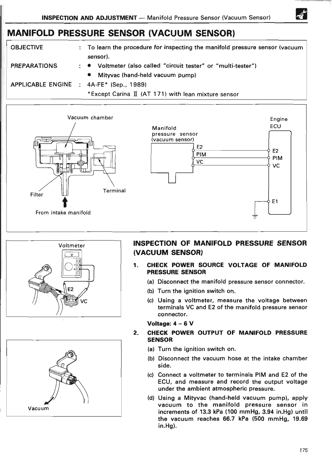
Vacuum chamber
E2
PIM
V
C
~
From intake manifold
INSPECTION OF MANIFOLD
PRESSURE SENSOR
(VACUUM
SENSOR
)
1
. CHECK POWER
SOURCE VOLTAGE
OF MANIFOLD
PRESSURE SENSO
R
(a) Disconnect the manifold pressure sensor connector
.
(b)
Turn the ignition switch on
.
(c) Using a voltmeter, measure the voltage between
terminals VC and E2 of the manifold pressure sensor
connector
.
Voltage
: 4 - 6
V
2
. CHECK POWER
OUTPUT OF
MANIFOLD PRESSURE
SENSO
R
(a) Turn the ignition switch on
.
(b) Disconnect the vacuum hose at the intake chamber
side
.
(c) Connect a voltmeter to terminals PIM and E2 of the
ECU, and measure and record the output voltage
under the ambient atmospheric pressure
.
(d) Using a Mityvac (hand-held vacuum pump), apply
vacuum to the manifold pressure sensor in
increments of 13
.3 kPa (100 mmHg, 3.94 in
.Hg) until
the vacuum reaches 66
.7 kPa (500 mmHg, 19
.69
in
.Hg)
.
175
 Loading...