INSPECTION AND ADJUSTMENT
- Distributo
r
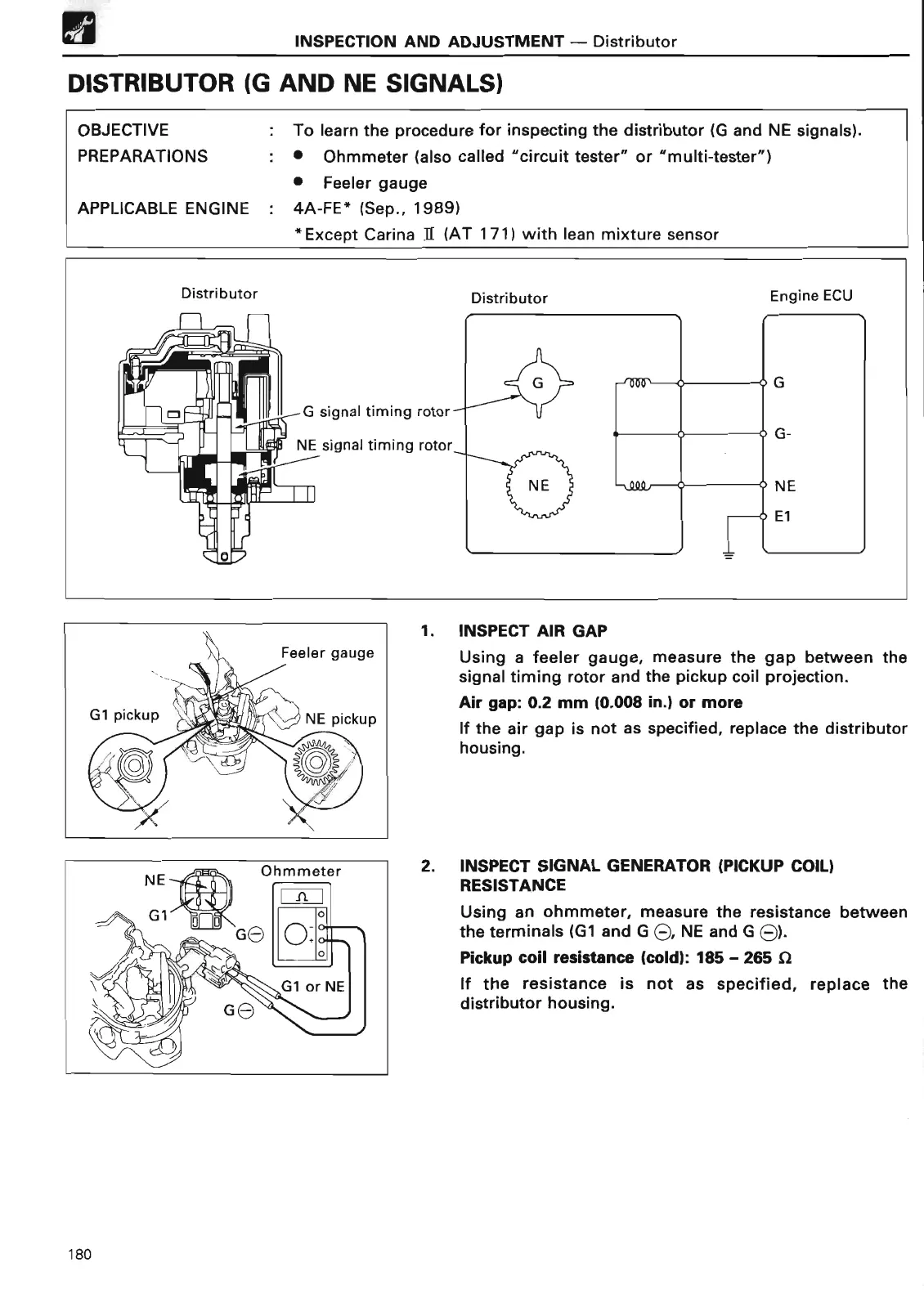
DISTRIBUTOR (G AND NE SIGNALS
)
OBJECTIVE
. To learn the procedure for inspecting the distributor (G and
NE signals)
.
PREPARATIONS
:• Ohmmeter (
also called
"circuit tester" or "multi-tester"
)
• Feeler gauge
APPLICABLE ENGINE
: 4A-FE* (Sep
., 1989
)
*Except
Carina II (AT 171) with lean mixture senso
r
1
. INSPECT AIR GA
P
Using a feeler gauge, measure the gap between the
signal timing rotor and the pickup coil projection
.
Air gap
: 0
.2 mm
(
0
.008 in
.) or mor
e
If the air gap is not as specified, replace the distributor
housing
.
2
. INSPECT SIGNAL
GENERATOR
(PICKUP COIL)
RESISTANC
E
Using an ohmmeter, measure the resistance between
the terminals (G1 and G G, NE and G 6)
.
Pickup coil resistance
(
cold)
: 185 - 265 S
2
If the resistance is not as specified, replace the
distributor housing
.
180
 Loading...