FAIL-SAFE FUNCTION
-
Fail-safe
Functio
n
FAIL-SAFE FUNCTIO
N
FAIL-SAFE FUNCTIO
N
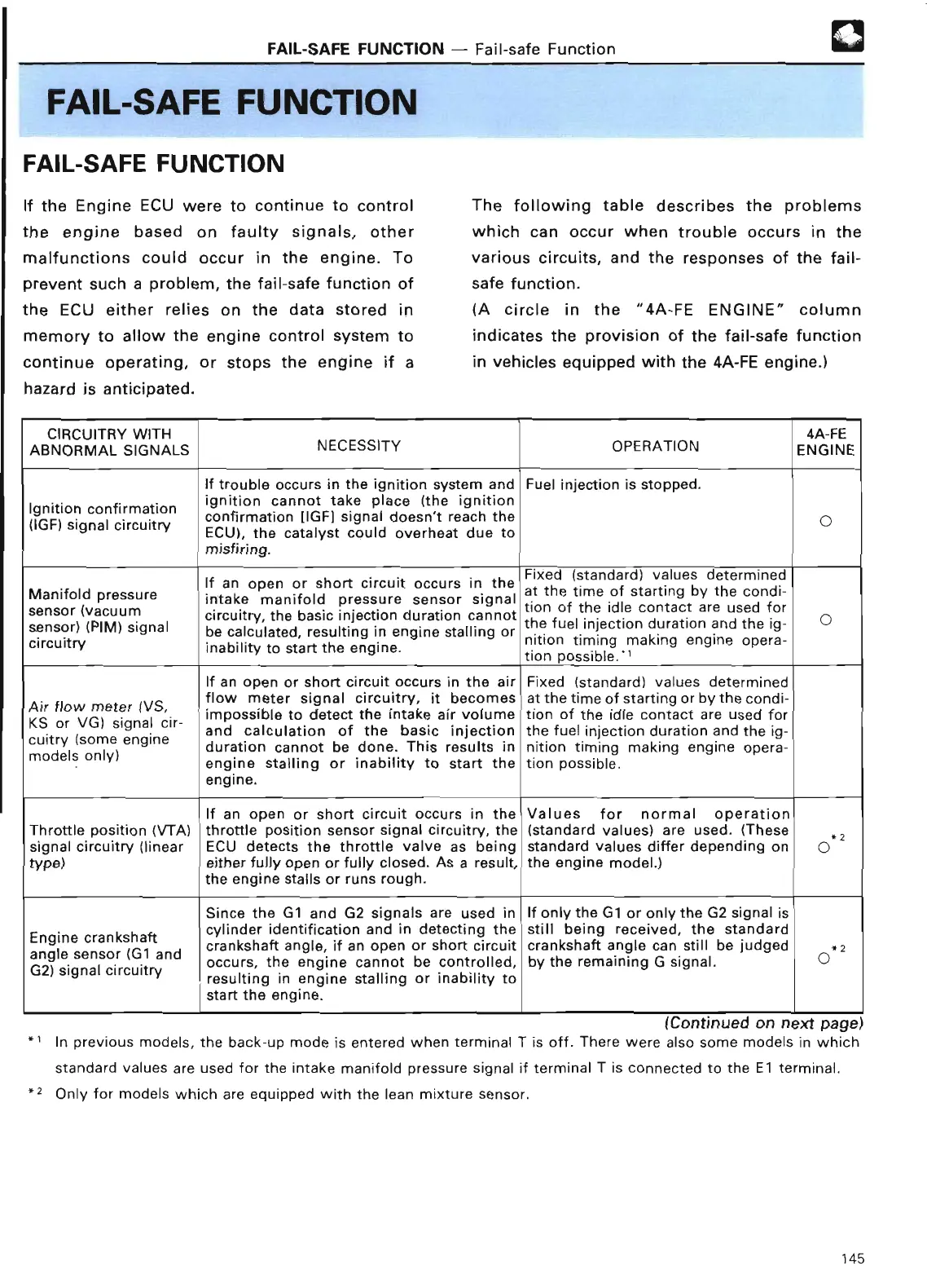
If the Engine ECU were to continue to control
the engine based on faulty signals, other
malfunctions could occur in the engine
. To
prevent such a problem, the fail-safe function of
the ECU either relies on the data stored in
memory to allow the engine control system to
continue operating, or stops the engine if a
hazard is anticipated
.
®
The following table describes the problems
which can occur when trouble occurs in the
various circuits, and the responses of the fail-
safe function
.
(A circle in the "4A-FE ENGINE" column
indicates the provision of the fail-safe function
in vehicles equipped with the 4A-FE engine
.
)
CIRCUITRY WITH
4A-F
E
ABNORMAL SIGNALS
NECESSITY OPERATION
ENGIN
E
If trouble occurs in the ignition system and
Fuel injection is stopped
.
Ignition confirmation
ignition cannot take place (the ignitio
n
'
t reach th
e
confirmation [IGF] signal doesn
0
(IGF) signal circuit
ry
ECU), the
catalyst
could overheat due t
o
misfiring
.
If an open or sho
rt
circuit occurs in the
Fixed (standard) values determine
d
at the time of starting by the condi
-
Manifold pressure
intake manifold pressure sensor signal
tion of the idle contact are used fo
r
sensor (vacuum
circuit
ry
, the basic injection duration cannot
the fuel injection duration and the ig-
0
sensor) (PIM) signal
be calculated, resulting in engine stalling or
nition timing making engine opera
-
circuit
ry
inability to sta
rt
the engine
.
tion possible
.
If an open or sho
rt
circuit occurs in the air
Fixed (standard) values determine
d
flow meter signal circuitry, it becomes
at the time of starting or by the
condi
-
Air flow meter (VS
,
Air
impossible to detect the intake air volume
tion of the idle contact are used fo
r
or VG) signal cir-
and calculation of the basic injection
ig
-
the fuel injection duration and the ig
-
cuitry
Isome engine
duration cannot be done
. This results in
nition timing making engine
opera
-
models only
)
models
stalling or inability to sta
rt
the
tion possible
.
engine
.
If an open or sho
rt
circuit occurs in the
Values for normal operatio
n
Thro
tt
le position (VTA)
thro
tt
le position sensor signal circuit
ry
, the
(standard values) are used
. (These
Z
signal circuit
ry
(linear
ECU detects the throttle valve as being
standard values differ depending on
0
type)
either fully open or fully closed
. As a result,
the engine model
.
)
the engine stalls or runs rough
.
Since the G1 and G2 signals are used in
If only the G1 or only the G2 signal i
s
cylinder identification and in detecting the
still being received, the standar
d
Engine crankshaft
crankshaft angle, if an open or sho
rt
circuit
crankshaft angle can still be judge
d
angle sensor (G1 and
occurs, the engine cannot be controlled,
by the remaining G signal
.
0
G2) signal circuit
ry
resulting in engine stalling or inability t
o
sta
rt
the engine
.
.
1
•2
(Continued on next page
)
In previous models, the back-up mode is entered when terminal T is off
. There were also some models in which
standard values are used for the intake manifold pressure signal if terminal T is connected to the
El
terminal
.
Only for models which are equipped with the lean mixture sensor
.
145
 Loading...