a
ELECTRONIC CONTROL SYSTEM - G and NE Signal Generator
s
3
. SEPARATE TYP
E
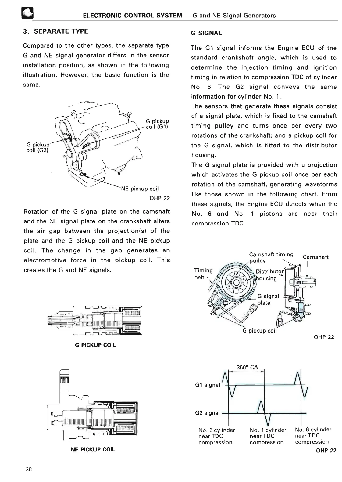
Compared to the other types, the separate type
G and NE signal generator differs in the sensor
installation position, as shown in the following
illustration
. However, the basic function is the
same
.
G pickup
coil (G2)
G pickup
coil (G1
)
NE pickup coil
OHP 2
2
Rotation of the G signal plate on the camshaft
and the NE signal plate on the crankshaft alters
the air gap between the projection(s) of the
plate and the G pickup coil and the NE pickup
coil
. The change in the gap generates an
electromotive force in the pickup coil
. This
creates the G and NE signals
.
L I IIIIIII Illr
.,d,l,„J
L~ _
I
G PICKUP COI
L
NE PICKUP COIL
G SIGNA
L
The G1 signal informs the Engine ECU of the
standard crankshaft angle, which is used to
determine the injection timing and ignition
timing in relation to compression TDC of cylinder
No
. 6
. The G2 signal conveys the same
information for cylinder No
. 1
.
The sensors that generate these signals consist
of a signal plate, which is fixed to the camshaft
timing pulley and turns once per every two
rotations of the crankshaft
; and a pickup coil for
the G signal, which is fitted to the distributor
housing
.
The G signal plate is provided with a projection
which activates the G pickup coil once per each
rotation of the camshaft, generating waveforms
like those shown in the following chart
. From
these signals, the Engine ECU detects when the
No
. 6 and No
. 1 pistons are near their
compression TDC
.
Camshaft timin
g
pulle
y
G1 signa
l
G2 signal
A
G pickup coi
l
3600
CA
N
No
. 1 cylinder
near TDC
compression
Camshaf
t
OHP 2
2
No
. 6 cylinder
near TDC
compressio
n
OHP 2
2
No
. 6 cylinder
near TDC
compressio
n
28
 Loading...