ELECTRONIC CONTROL SYSTEM
- Power Circuitry, VC Circuitry, Ground Circuitr
y
2
. ENGINE WITH STEPPER MOTOR TYPE
ISC VALV
E
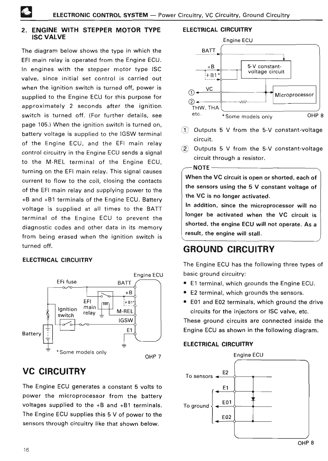
The diagram below shows the type in which the
EFI main relay is operated from the Engine ECU
.
In engines with the stepper motor type ISC
valve, since initial set control is carried out
when the ignition switch is turned off, power is
supplied to the Engine ECU for this purpose for
approximately 2 seconds after the ignition
switch is turned off
. (For further details, see
page 105
.) When the ignition switch is turned on,
battery voltage is supplied to the IGSW terminal
of the Engine ECU, and the EFI main relay
control circuitry in the Engine ECU sends a signal
to the M-REL terminal of the Engine ECU,
turning on the EFI main relay
. This signal causes
current to flow to the coil, closing the contacts
of the EFI main relay and supplying power to the
+B and +B1 terminals of the Engine ECU
. Battery
voltage is supplied at all times to the BATT
terminal of the Engine ECU to prevent the
diagnostic codes and other data in its memory
from being erased when the ignition switch is
turned off
.
ELECTRICAL CIRCUITR
Y
EFI fus
e
Battery
Engine ECU
ELECTRICAL CIRCUITR
Y
Engine EC
U
Some
models only
OHP
8
1 Outputs 5 V from the 5-V constant-voltage
circuit
.
2 Outputs 5 V from the 5-V constant-voltag
e
circuit through a resistor
.
~ NOT
E
When the VC circuit is open or shorted, each of
the sensors using the 5 V constant voltage of
the VC is no longer activated
.
In addition, since the microprocessor will no
longer be activated when the VC circuit is
shorted, the engine ECU will not operate
. As a
result, the engine will stall
.
GROUND
CIRCUITR
Y
The Engine ECU has the following three types of
basic ground circuitry
:
•
El
terminal, which grounds the Engine ECU
.
• E2 terminal, which grounds the sensors
.
• E01 and E02 terminals, which ground the drive
circuits for the injectors or ISC valve, etc
.
These ground circuits are connected inside the
Engine ECU as shown in the following diagram
.
ELECTRICAL CIRCUITR
Y
VC CIRCUITR
Y
Some models only
OHP 7
Engine ECU
/I
-
E2
The Engine ECU generates a constant 5 volts to
power the microprocessor from the battery
voltages supplied to the +B and +B1 terminals
.
The Engine ECU supplies this 5 V of power to the
sensors through
circuitry
like that shown below
.
To sensors
.
E
l
To ground E01
OHP
8
E0
2
16
 Loading...