ELECTRONIC CONTROL SYSTEM
- Vehicle Speed Senso
r
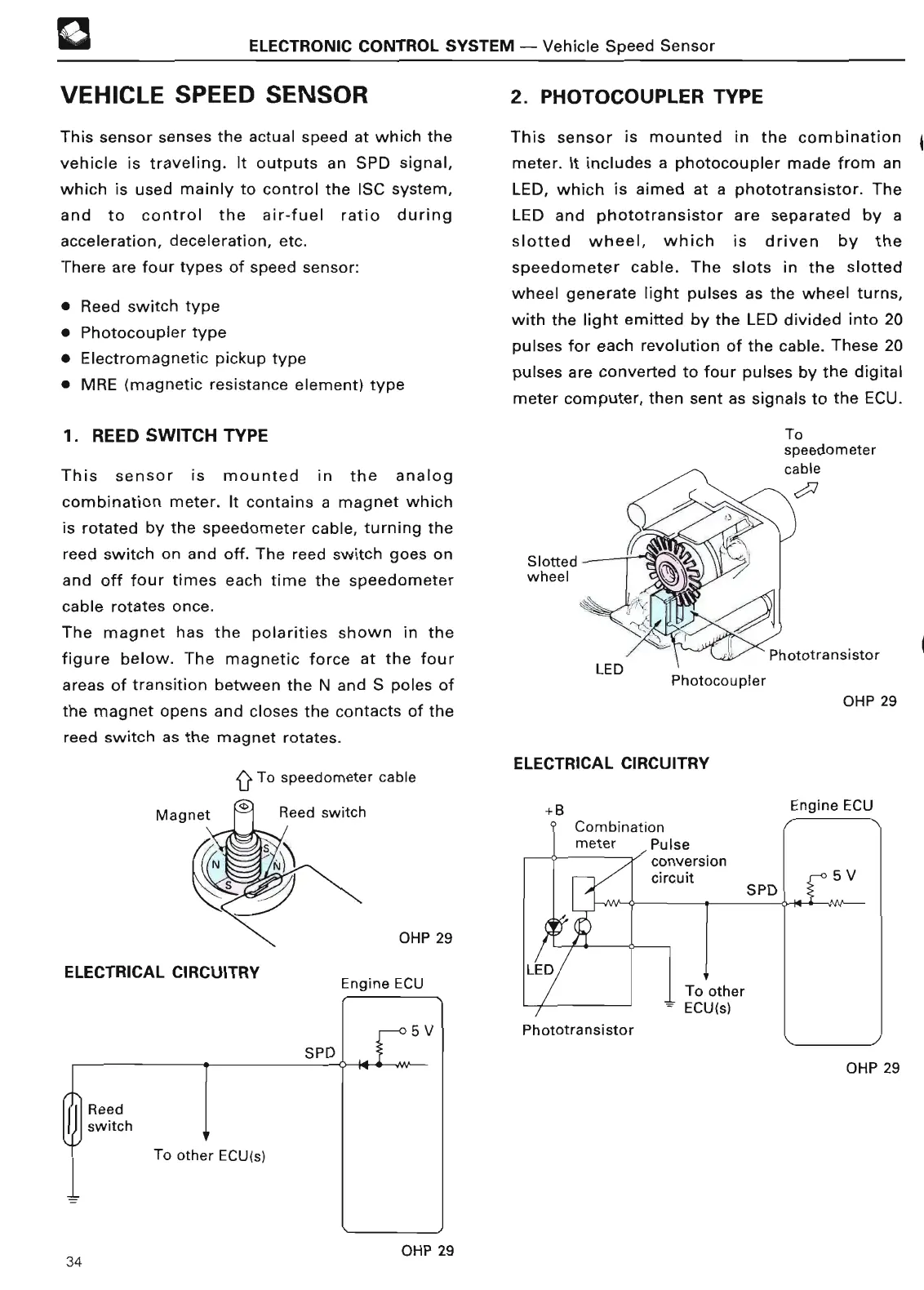
VEHICLE SPEED SENSO
R
This sensor senses the actual speed at which the
vehicle is traveling
. It outputs an SPD signal,
which is used mainly to control the ISC system,
and to control the air-fuel ratio during
acceleration, deceleration, etc
.
There are four types of speed sensor
:
• Reed switch type
• Photocoupler typ
e
• Electromagnetic pickup typ
e
• MRE
(magnetic resistance element) typ
e
1
. REED
SWITCH TYP
E
This sensor is mounted in the analog
combination meter
. It contains a magnet which
is rotated by the speedometer cable, turning the
reed switch on and off
. The reed switch goes on
and off four times each time the speedometer
cable rotates once
.
The magnet has the polarities shown in the
figure below
. The magnetic force at the four
areas of transition between the N and S poles of
the magnet opens and closes the contacts of the
reed switch as the magnet rotates
.
Q To speedometer cabl
e
OHP 2
9
ELECTRICAL CIRCUITRY
Engine ECU
2
. PHOTOCOUPLER TYP
E
This sensor is mounted in the combination
meter
. It includes a photocoupler made from an
LED, which is aimed at a phototransistor
. The
LED and phototransistor are separated by a
slotted wheel, which is driven by the
speedometer cable
. The slots in the slotted
wheel generate light pulses as the wheel turns,
with the light emitted by the LED divided into 20
pulses for each revolution of the cable
. These 20
pulses are converted to four pulses by the digital
meter computer, then sent as signals to the ECU
.
Slo
tt
ed
wheel
OHP 29
ELECTRICAL CIRCUITR
Y
+B
Combination
meter Puls
e
Phototransistor
conversio
n
circuit
Engine EC
U
OHP 2
9
34 OHP 29
 Loading...