UNT-SVX07B-EN 11 5
Diagnostics
feature is on models with both hydronic and electric heat. Low vertical models with electric heat,
switch SW4 to position 2 (on).
Troubleshooting Wireless Controls
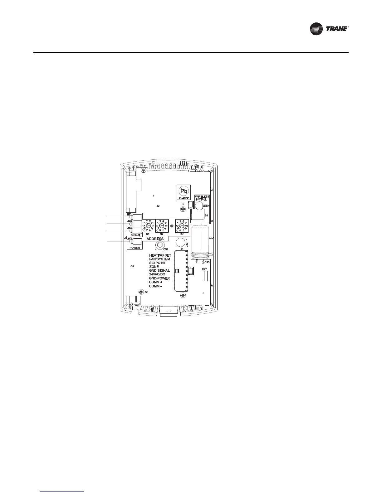
Locations of LEDs, Test button, Test Symbols, and Error Codes
The receiver for all models has four LEDs: LED1, LED2, LED3, and LED5. Figure 30 shows their
locations.
Note: To view LEDs on a flush mount receiver on a fan-coil unit, the front panel of the unit must
be removed.
The sensor for model WTS have four LEDs: LED1, LED2, LED3, and LED5. The sensor for model
WDS has test symbols and error codes that appear on the display. All three sensor models have
a Test button. Figure 31 shows their locations.
Figure 30. LED locations on the receiver
 Loading...