UNT-SVX07B-EN 69
Controls Interface
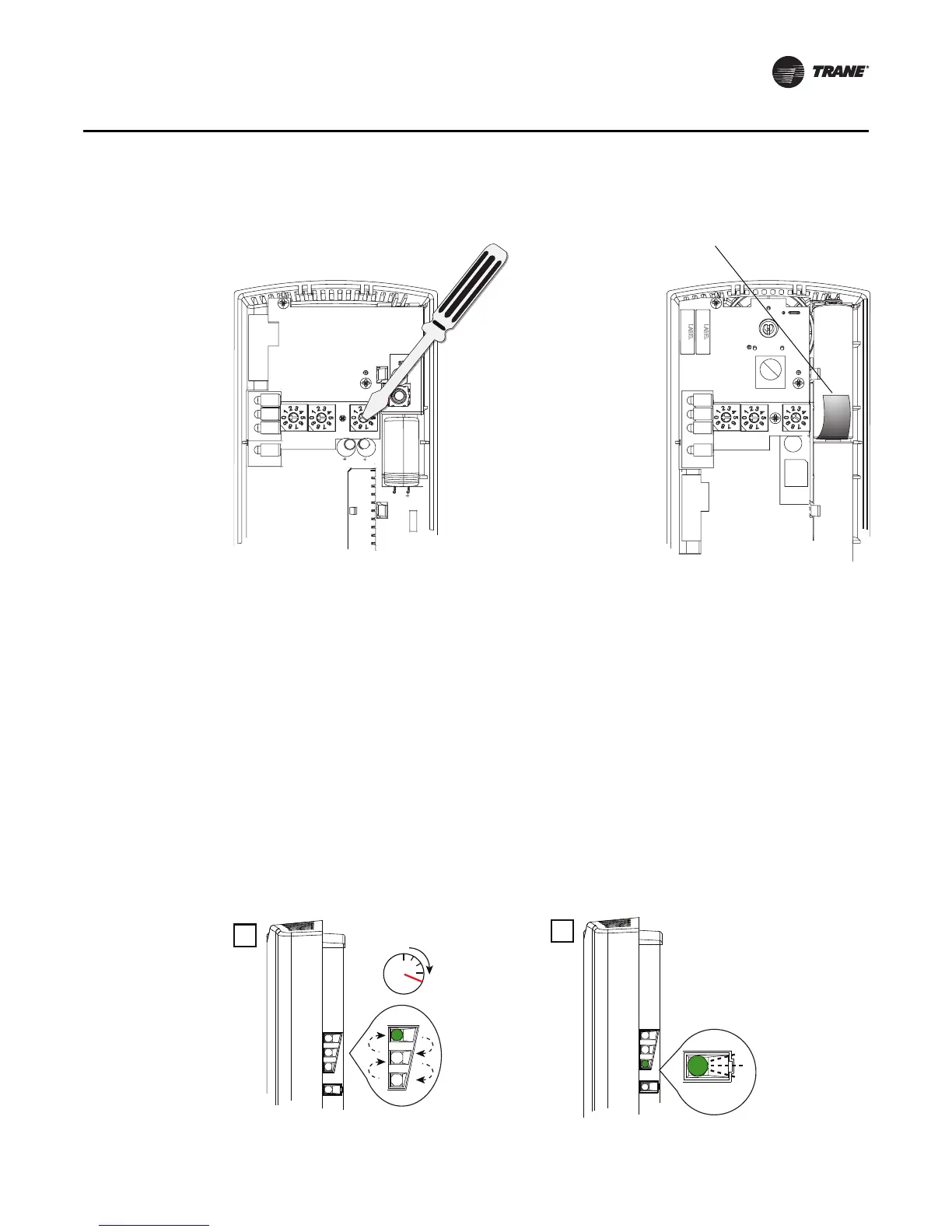
2. Set the three rotary address switches (locations S1, S2, S3) on the sensor to the same address
as the receiver (see Figure 19).
Note: Do not use
000 as an address. An address of 000 removes all association knowledge,
reverts the sensor to a low-power hibernation mode, and sends a disassociation request
to the receiver.
3. Record the address and l
ocation of the receiver and sensor pair.
Observing the Receiver for Readiness to Associate
After initial power up, the receiver conducts a channel scan for 20 seconds. During this time, the
receiver selects from 16 available channels the clearest channel on which to operate. LED1, LED2,
and LED3 flash rapidly in succession (round-robin style) while the channel scan is in progress, as
shown in part 1 of the illustration.
Important: Do not attempt association (leave the insulation strip in place) until the channel scan
is finished.
After the channel scan is finished, LED3 begins blinking (one-blink pattern) to show that the receiver
is ready to be associated with a sensor (see part 2 of the following figure).
Figure 19. Setting the rotary address switches on the receiver and the sensor
S5
GND
R77
C35
S1
S2
C33
LED4
S4
S5
S3
LED1
LED2
LED3
LED5
C34
J1
COMM -
24VAC/DC
SETPOINT
HEATING SET
SIGNAL
POWER
ADDDRESS
FAN/SYSTEM
ZONE
COMM +
INS
T
A
L
L
WIRELESS
GND
B1 +
INSTALL
WIRELESS
S4
S3
S2
S1
ADDRESS
STATUS
BATTERY
LED5
SIGNAL
LED3
L
ED2
LED1
Pb
Pb-FREE
STATUS
LED4
Do not remove the
insulation strip yet.
Receiver Sensor
 Loading...