UNT-SVX07B-EN 83
Start-Up
Tracer™ ZN510 & ZN520 Unit Startup
Refer to the Trane publication, CNT-IOP-1 (ComfortLink 10 Controller: Installation, Operation and
Programming Guide) for Tracer ZN510 and CNT-SVX04A-EN for Tracer ZN520. The factory pre-
programs the Tracer ZN510 and ZN520 with default values to control the temperature and unit
airflow. Use Tracer Summit building automation system or Rover™ software to change the default
values.
Follow the procedure below to operate the Tracer ZN510 or ZN520 in a stand-alone operation:
1. Turn power on at the disconnect switch option.
2. Position the fan mode switch to either high, medium, low, or the auto position.
3. Rotate the setpoint dial on the zone sensor module to 55°F for cooling or 85°F for heating.
The appropriate control valve will actuate
assuming the following conditions:
1. Room temperature should be greater than 55°F and less than 85°F.
2. For a 2-pipe fan-coil unit with an automa
tic changeover sensor, the water temperature input is
appropriate for the demand placed on the unit. For example, cooling operation is requested and
cold water (5° lower than room temperature)
flows into the unit.
3. Select the correct temperature setpoint.
Note: Select and enable zone sensor temperature settings to prevent freeze damage to unit.
General Information
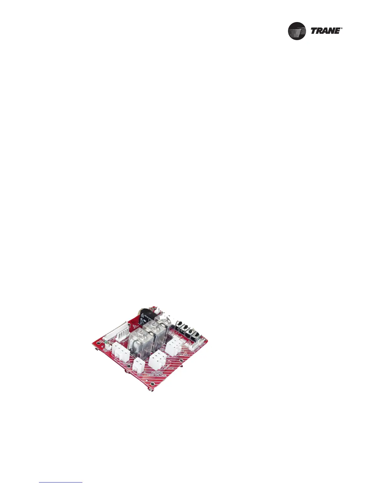
Relay (Daughter) Board
The relay board is a new component on all models (except those with a unit-mounted, line-voltage
fan speed switch) that replaces all the loose wires in the control box. It consolidates many control
components onto one board, therefore making it easy to troubleshoot in the field. There is an LED
on the board that indicates when power is supplied to the board. All connections are made to match
up only with the applicable component to, thus prevent miswiring. Factory switches are pre-set and
locked in place with lock-tight. The switch settings can be broken if field-modifications are needed.
However, switches must be properly set for the unit to operate safely and properly. See Figure 21.
Manual Fan Mode Switch
The manual fan mode switch is available with a four-position switch (off-hi-med-lo) allows manual
fan mode selection and is available unit- or wall-mounted. See Figure 22.
Figure 21. Relay board
 Loading...