FAI Connections
6–28 iSTAR Ultra Installation and Configuration Guide
Tolerance if sourced by an external power supply.
To determine the maximum distance of a reader from an iSTAR Ultra, calculate the voltage
that reaches each reader. If the voltage is insufficient, you can shorten the wire length, use a
heavier wire, or add UL294 power-limited power supply.
Wire resistance is as follows:
• 24 AWG = 26.0 per 1000 ft.
• 22 AWG = 16.5 per 1000 ft.
• 20 AWG = 10.2 per 1000 ft.
• 18 AWG = 6.5 per 1000 ft.
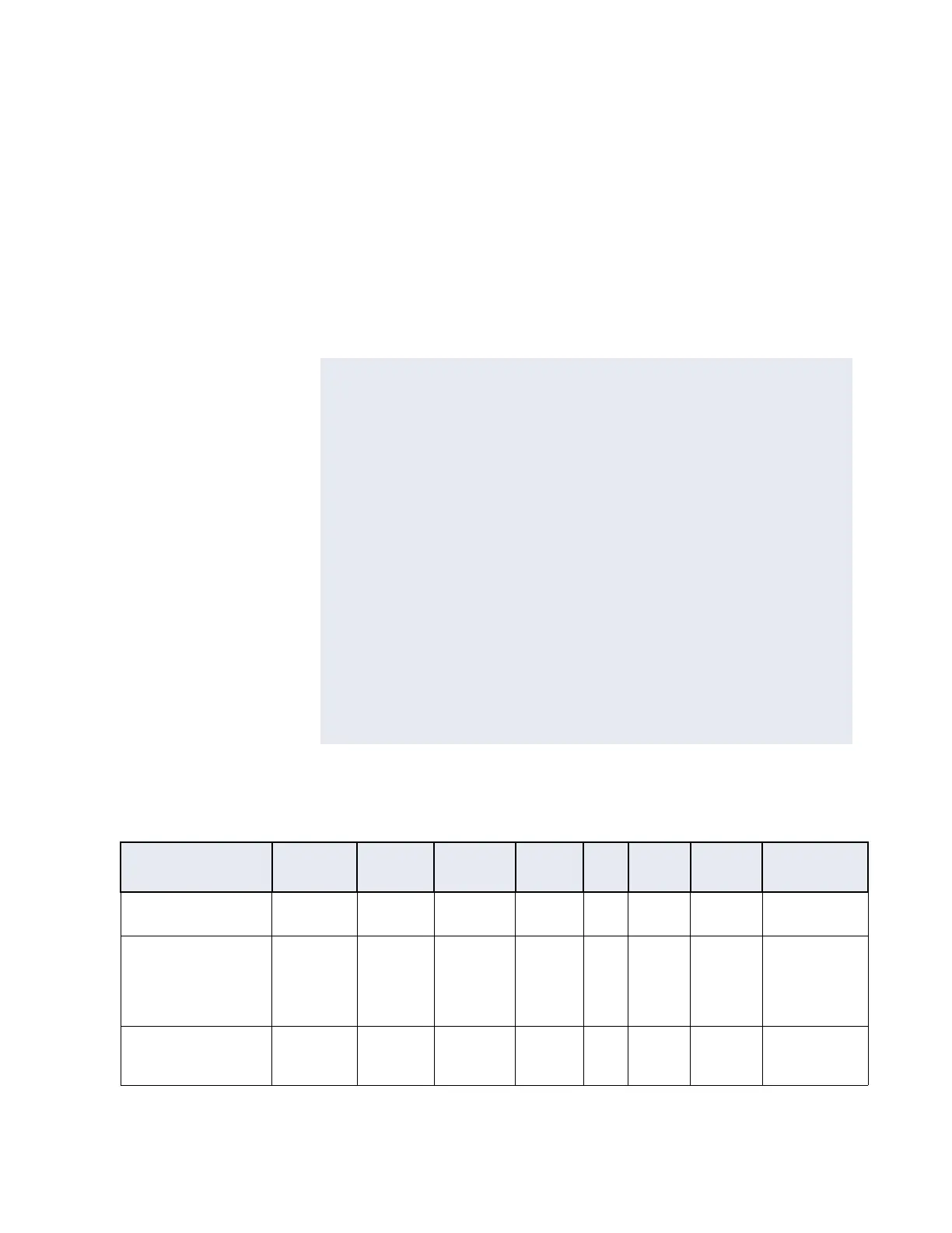
Table 6-9 on page 6-28 lists the general wiring requirements for an iSTAR Ultra and its
components.
NOTE
You must consider the wire length both to and from the reader, in the
calculation.
Example:
•The RM-4 is 500 feet away. (1000' round trip)
•The RM-4 draws 250 mA. and is connected with 20 AWG wire.
The equation to calculate voltage drop is:
E= I*R
I = .25 A (250 mA)
R= 10.2 ohms (from the table)
E= .25 * 10.2
E= 2.55 (voltage drop)
12 Vdc - 2.55 Vdc = 9.45 Vdc
The connection meets the requirement.
x
Table 6-9: Equipment Wiring Specifications
Signal From To
Belden #
or equiv.
AWG
#
Prs
Shield
Max
Length
Max. Wire
Resistance
RS-485 Comm, Data
Half-duplex 2 wire
iSTAR Ultra RM & I/O
Modules
9841 24 1 Yes 4000 ft.
(1212 m)
103
RS-485 Comm, Power iSTAR Ultra RM & I/O
Modules
8442/8461 22/18 1 Yes Range of
600 ft. to
1500 ft.
depends
on AWG
See Note
2
RJ45-Ethernet iSTAR Ultra Hub, Host N/A Shielded
Cat-5E
or better
2 Yes 328 ft.
(100 m)
8.4

 Loading...