FAI Connections
iSTAR Ultra Installation and Configuration Guide 6–29
Supervised Input iSTAR Ultra
or I8
Input 8442/8461 22/18 1 No 2000 ft.
(606 m)
Request-to-exit
(REX or RTE)
iSTAR Ultra
or RM-4/4E
module
Switch 8442/8461 22/18 1 No 2000 ft.
(606 m)
Door State Monitor
(DSM)
iSTAR Ultra
or RM-4/4E
module
Contact 8442/8461 22/18 1 No 2000 ft.
(606 m)
Supervised Input (UL)
Note
1
iSTAR Ultra
or I8
Input 9462 22 1 Yes 2000 ft.
(606 m)
Relay Control RM-4
module
ARM-1 9462 22 1 Yes 25 ft.
(7.6 m)
.04
Reader Data (Direct
Wiegand Connection)
iSTAR
Ultra or
RM-4/4E
module
Proximity/
Wiegand
signaling
read head
9942
9260
Alpha wire
5386C
22
20
18
3 Yes 200 ft.
(60.96 m)
300 ft.
(91.4 m)
500 ft.
(152.4 m)
3.2
3.2
3.2
1
To comply with UL requirements, use shielded, minimum 22 AWG stranded, twisted pair cable for monitor points, supervised inputs, DSMs, and REXs.
Use Belden9462 or equivalent
.
2
Check wire lengths to verify that voltage drops are acceptable.
Calculations are based on a single RM-4 reader with keypad and LCD (250 mA):
Using 22 AWG, distance = 600 ft. (.0165 W /ft.)
Using 18 AWG, distance = 1500 ft. (.0065 W /ft.)
NOTE
Cables that need to be shielded are described in Table 6-9 on page 6-28.
The Tamper, Low Battery, and AC power fail inputs must be enabled and
connected to the iSTAR Ultra to report for compliance with UL requirements.
For UL listed products, burglar alarm inputs must be supervised.
UL Listed panic hardware shall be used to allow emergency exit from a
protected area.
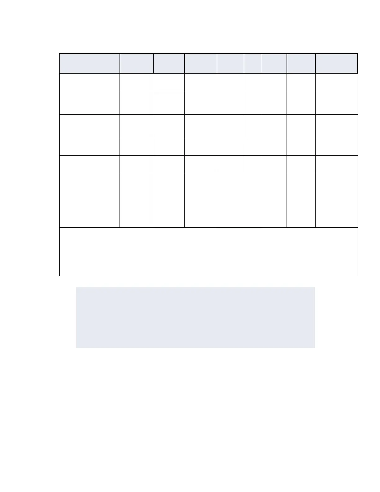
Table 6-9: Equipment Wiring Specifications, continued
Signal From To
Belden #
or equiv.
AWG
#
Prs
Shield
Max
Length
Max. Wire
Resistance

 Loading...