Installation
2–6 iSTAR Ultra Installation and Configuration Guide
2. Open the enclosure door and disconnect the grounding wire on the door.
3. Carefully lift the door off the hinges, and place it on a padded surface.
4. Verify that the upper mounting screws (or equivalent) are in place on the mounting site
for the keyhole locations.
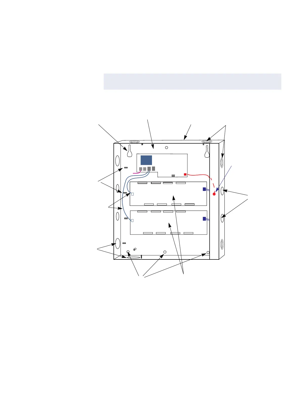
Figure 2-1: iSTAR Ultra Controller with Door Removed (Two ACMs Mounted)
LCD
5. Align the mounting keyhole slots at the upper back of the enclosure with the two upper
mounting screws, and lower the enclosure into position.
6. Install the three lower mounting screws and the remaining top mounting screw in
between the two keyhole mounts.
7. Attach the conduit couplings to the knockout openings as needed to comply with local
code requirements.
8. Reattach the grounding wire between the door and the enclosure.
NOTE
See Figure 2-1 on page 2-6 for the location of the keyhole slots, screws, and
knockouts.
Ground Stud
(6-32)
For Shield Wire,
1 By Each Knockout
Assorted Knockouts
Cabinet/Enclosure
General Controller
Module (GCM)
Access
Control
Module
(ACM)
Assorted
Knockouts
Keyhole
Mounting
Slot (2)
Lower Mounting
Hole (3)
Tamper Switch
Assorted
Knockouts
USB Cables
ACM 1
ACM 2
GCM
E-Net
Tamper
LCD
LCD
Reader & Logic Power
Reader & Logic Power
Note: ACM Lock
Power IN supplies
the WET relay outputs.

 Loading...