Illustration 6 : Using the X-Y function
To check the phase difference between two channels.
Example : To measure the phase variation when a
signal passes through the circuit, connect your
oscilloscope to the circuit and monitor the input and
output signals. To check the circuit s input and output
in the X-Y coordinate mode, follow the steps below :
1. Set the attenuation factor of the probe to 10X. Set
the switch of the probe to 10X.
2. Connect the CH1 probe to the input terminal of
the network. Connect the CH2 probe to the
output terminal of the network
3. If the channel is not displayed, press the [CH1]
and [ ] menu button to enable the two
5. Adjust the vertical knob to make the
displayed amplitude of the two channels to
6. Press the [ ] menu key to recall the
7. Press [ ] to select X-Y The oscilloscope will
display the circuit s input and output
characteristics in a Lissa jous figure.
8. Adjust the vertical scale and vertical position
knob to achieve the best result of waveform.
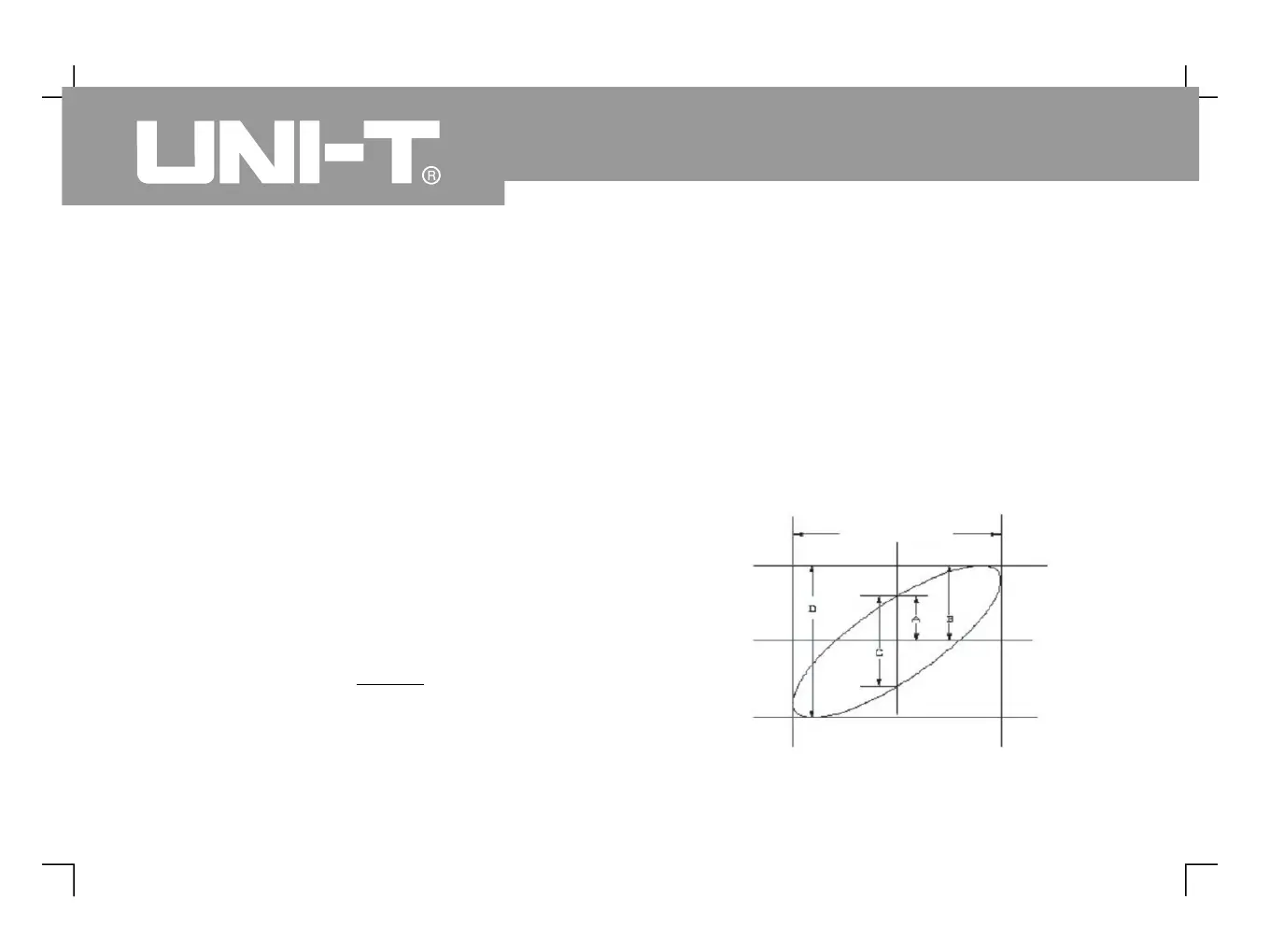
9. Using the elliptic oscilloscope display graph to
observe, measure and calculate the phase
 Loading...