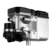
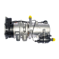
3 Description of Operation DBW 2010 / 2016
301
3 Description of Operation
3.1 General information
The heaters equipped with a high-pressure atomizing burner
operate in the intermittent mode.
Control is carried out either
– thermostatically (heaters with 1553 control unit) or
– with temperature sensor (DBW 2010 heaters with sensor
technology with 1563/1564 control unit).
3.2 Operation
The heater is switched on and off with
– switch (On/Off) or
– digital timer.
To monitor the operating sequence, an operating indicator
lamp is installed in the digital timer or separately.
On request, the heaters can be equipped with
– a nozzle holder pre-heating unit with a heating cartridge
for extremely low temperatures,
There is a partially altered operating sequence for heaters
with sensor technology (see Fig. 302).
3.2.1 Switching on
When the heater is switched on, the operating indicator lamp
lights up. The combustion air fan, fuel pump and circulation
pump start up. After approx. 15 seconds, the solenoid valve
is opened, and fuel is sprayed into the combustion chamber
via the atomiser nozzle and ignited by a simultaneously trig-
gered high-voltage ignition spark. With a signal of the flame
monitor, the control unit switches the ignition spark genera-
tor off again after a flame has been formed.
If no combustion is produced, see 3.2.4.
3.2.2 Heating mode
After the operating temperature is reached, the control mode
is assumed by the control thermostat (or by the control unit
with heaters with sensor technology).
Alternately switching on and off maintains the heat
exchanger (coolant) temperature at a constant level. If the
temperature exceeds the upper switch point, the solenoid
valve shuts off the fuel supply, causing the flame to go out.
The run-on begins, during which the combustion air fan con-
tinues to run and is switched off automatically after approx.
150 (or 90 for heaters with sensor technology) seconds. The
circulation pump remains in operation in the control break
and the operating indicator lamp lights up. If the temperature
drops below the lower switch point, the new heater start-up
process begins.
3.2.3 Switch off
Combustion ends when the heater is switched off. The oper-
ating indicator lamp goes out and the run-on begins. The
combustion air fan and the circulation pump are switched off
after approx. 150 (or 90 for heaters with sensor technology)
seconds.
It is permissible to switch on the heater again during the run-
on.
3.2.4 Fault switch-off
For heaters with 1553 and 1563/64 control unit
A fault switch-off is carried out
– if no combustion occurs within approx. 30 seconds after
the heater is switched on,
– if the combustion-air supply during the heating mode is
interrupted for longer than 10 seconds,
– by the thermal fuse or the overheating temperature lim-
iter if the heater overheats. Then an identical thermal
fuse must be used as a replacement (observe colour cod-
ing) or a reset must be carried out with the button of the
temperature limiter (after cooling down to below 60 °C).
Fault switch-off for heaters with 1553 control unit
– in case of undervoltage approx. 10 to 25 seconds after
the switching threshold is dropped below.
 Loading...


