6Operating Tests DBW 2010 / 2016
604
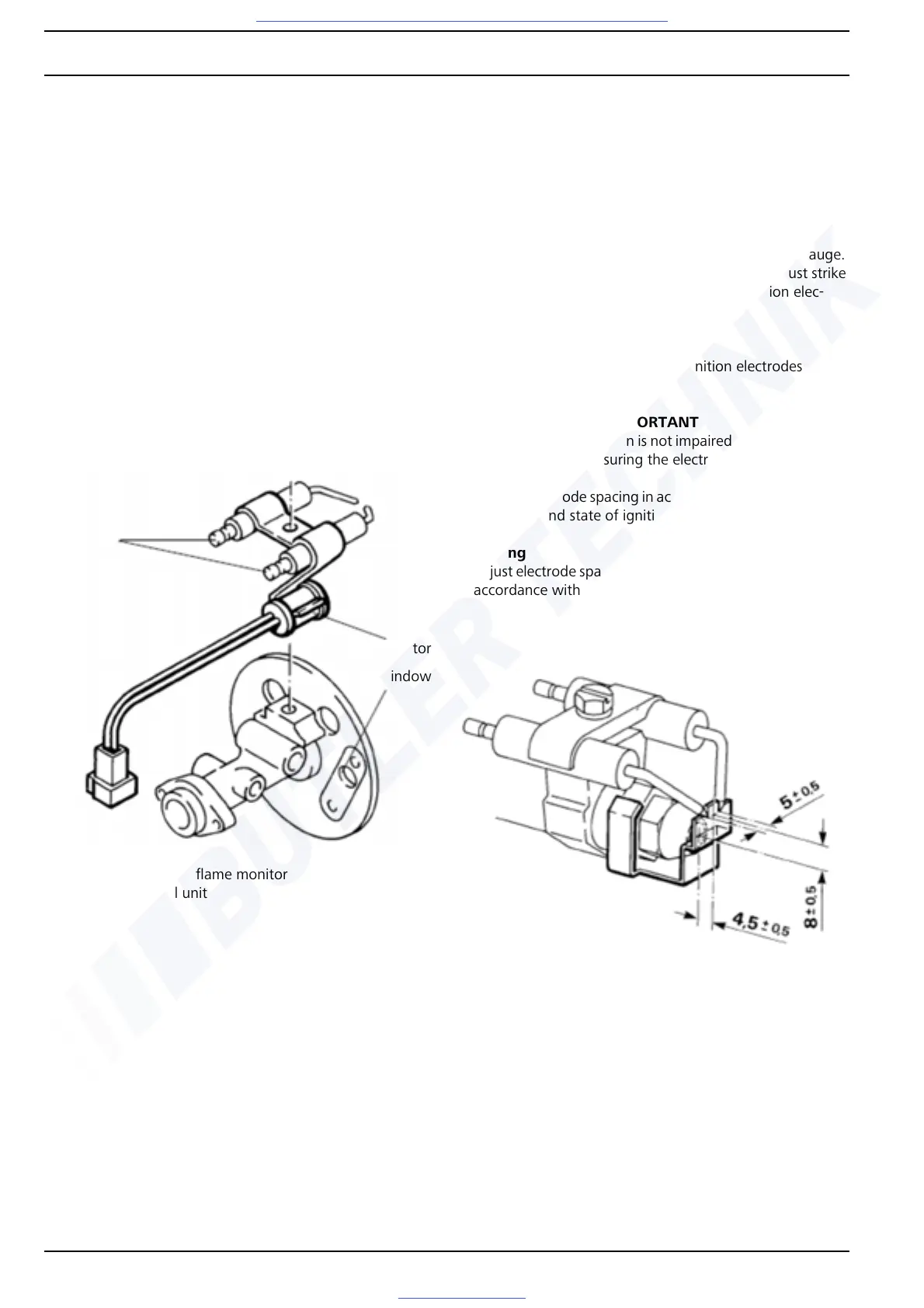
6.3.2.2 Checking flame monitor with 1563/1564
control unit
When installed
– Connect voltmeter to connections D6 (+) and D7 (–) of
control unit
– Switch on heater
– The measured voltage must be 5 V.
After approx. 15 s to 26 s, the voltage must drop to
<1V.
When removed
– Connect flame monitor with a series resistor of 1 kohms
to 5 V
– Connect voltmeter parallel to flame monitor
– The voltage must drop to > 1 V with the lens darkened
and an open flame or light bulb (5 W).
6.3.3 Checking and setting ignition electrodes
NOTE
• The insulating elements of the ignition electrodes must
not be damaged. Ignition electrodes with an electrode
spacing outside the tolerance or ignition electrodes
which do not operate properly must be adjusted or re-
placed.
• The ignition electrodes can be adjusted with the gauge.
For this purpose, the front edge of the gauge must strike
the atomising nozzle and the tip of the ignition elec-
trodes must be in the two notches.
Test
– Examine insulating element of ignition electrodes for
damage.
IMPORTANT
So that the fuel atomisation is not impaired, do not touch the
nozzle hole when measuring the electrode spacing.
– Check electrode spacing in accordance with gauge as per
Fig. 608 and state of ignition electrodes.
Adjusting
Readjust electrode spacing by bending and check with gauge
in accordance with Fig. 608.
Fig. 607 Checking flame monitor with 1563/1564
control unit
 Loading...


