Home
Webasto
Water Heater
DBW 2010
Webasto DBW 2010 Workshop Manual
4
of 1
of 1 rating
78 pages
Give review
Manual
Specs
To Next Page
To Next Page
To Previous Page
To Previous Page
Loading...
7
Circuit Diagrams
DBW 2010 / 2016
704
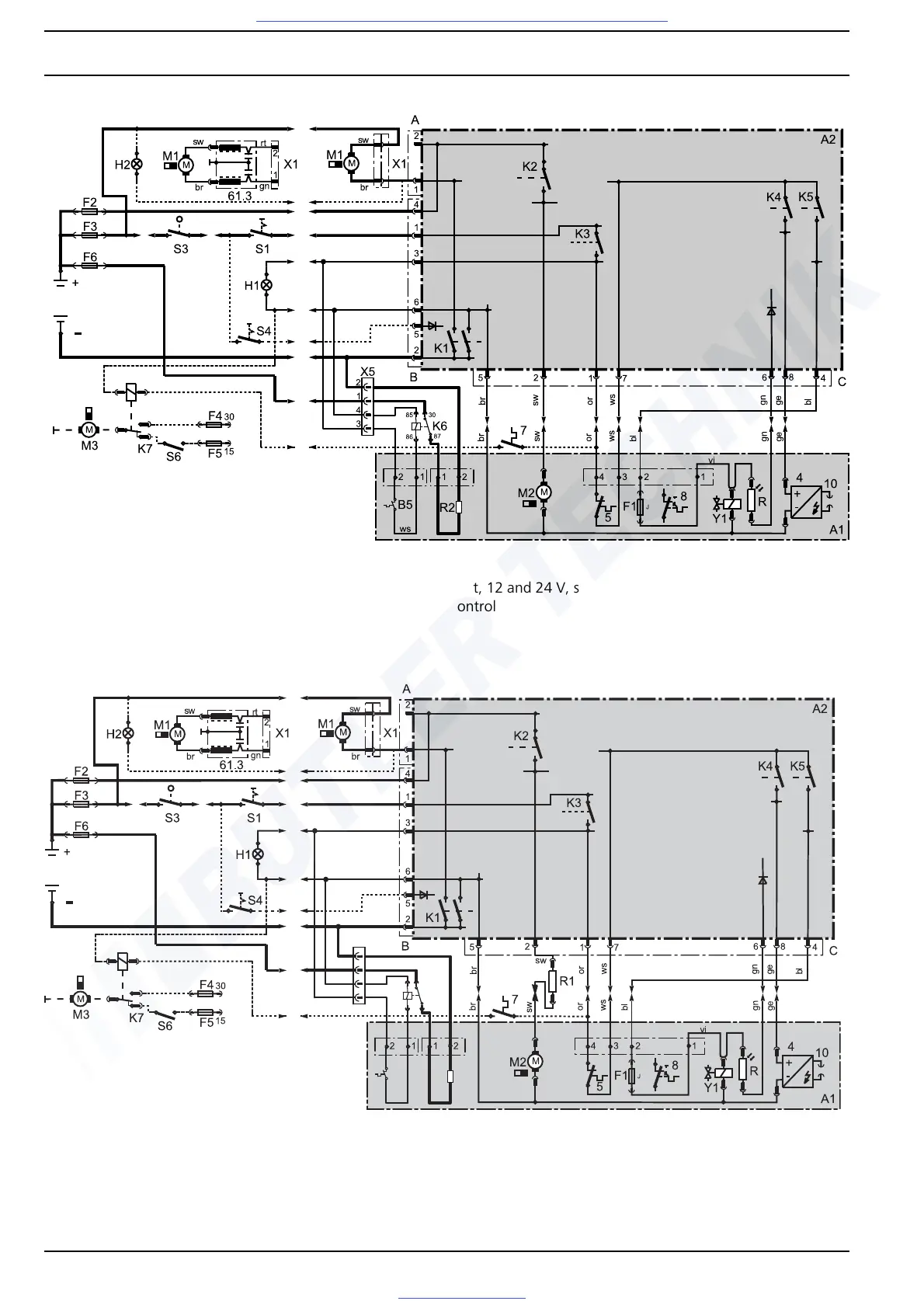
Fig. 703 System wiring diagram DBW
20
10 with 1553 control
uni
t,
12 and 24 V, s
witch, nozzle holder pre-heating unit and
altitude c
on
trol
Fig. 704 System wiring diagram DBW
2016 with 1553 control un
it, 24 V, switch, nozzle holder
pre-heating unit and altitude
control
B5
R2
ws
X5
1
2
3
4
87
30
85
86
K6
Visit www.butlertechnik.com for more technical information and downloads.
www.butlertechnik.com
42
44
Table of Contents
Default Chapter
1
Water Heaters
1
Table of Contents
4
1 Introduction
8
Statutory Regulations Governing Installation
9
Suggestions for Improvement and Change
11
2 General Description
12
Fig. 201 DBW 2010 Heaters
13
Fig. 202 DBW 2010 Heaters with Sensor Technology
14
Fig. 203 DBW 2016 Standard / Rail Heaters
15
Fig. 204 Combustion Air Fan
16
Fig. 205 Motor
16
Fig. 206
16
Fig. 207
16
Fig. 208 Heat Exchanger
17
Fig. 209 Combustion Chamber
17
Fig. 210 1553 Control Unit
17
Fig. 211 1563/1564 Control Unit for Heaters with Sensor Technology
17
Fig. 212 Flame Monitor Standard Device
18
Fig. 213 Flame Monitor Heaters with Sensor Technology
18
Fig. 214 Ignition Spark Generator with Ignition Electrodes
18
Fig. 215 Temperature Sensor (Sensor Technology Variant)
18
Fig. 216 Temperature Limiter/Thermal Fuse Only for Heaters with 1563/1564 Control Unit
19
Fig. 217 Control Thermostat on Heater
19
Fig. 218 External Control Thermostat
20
Fig. 219 Fan Thermostat on Heater
20
Fig. 220 Fan Thermostat in Coolant Circuit
20
Fig. 221
20
3 Description of Operation
21
Fig. 301 Operating Sequence (Heaters with 1553 Control Unit)
22
Fig. 302 Operating Sequence (Heaters with 1563/1564 Control Unit)
23
4 Technical Data
24
Fig. 501 General Error Symptoms
26
5 Troubleshooting
26
Fig. 502 Troubleshooting - Rapid Diagnosis
28
Malfunction Symptoms
29
When Switched on
30
Heater Does Not Start until after Several Starting Attempts
31
Heater Emits Black Smoke
32
Heater Emits White Smoke
33
Fig. 601
34
Fig. 602
34
6 Operating Tests
34
Fig. 603
35
Fig. 604
35
Fig. 605 Resistance Test of Temperature Sensor
36
Fig. 606 Checking Flame Monitor with 1553 Control Unit
36
Checking Individual Components
36
Fig. 607 Checking Flame Monitor with 1563/1564 Control Unit
37
Fig. 608 Reassigning and Checking Electrode Spacing
37
Checking and Setting Ignition Electrodes
37
Fig. 609 Fuel Pump Pressure
38
Checking Ignition Spark Generator
38
Checking Burner Motor
39
7 Circuit Diagrams
40
Fig. 703 System Wiring Diagram DBW 2010 with 1553 Control Unit, 12 and 24 V, Switch, Nozzle Holder
43
Fig. 704 System Wiring Diagram DBW 2016 with 1553 Control Unit, 24 V, Switch, Nozzle Holder
43
Work on Vehicle
47
Fig. 801 Swinging Burner Head Away and in
48
Visual Inspections and Installation Instructions
49
Fig. 802 Installation Example for Heater in Bus
50
Fig. 803 Notification Sign
51
Combustion Air Supply
51
Removal and Installation
52
Replacing Thermal Fuse
53
Start-Up
54
9 Repair
55
Fig. 901 Visual Inspection on Combustion-Air Rotor
56
Works on Components When Dismantled
56
Fig. 902 Installing Nozzle Holder Pre-Heating Unit with 1553 Control Unit
57
Fig. 903 Retrofitting DBW 2010 / DBW 2016
58
Fig. 904 Electrical Connection
59
Fig. 905 Installing Nozzle Holder Pre-Heating Unit with 1563/1564 Control Unit
60
Fig. 906 Retrofitting DBW 2010
61
Fig. 907 Electrical Connection
62
Replacing Thermal Fuse
63
Fig. 908 Replacing Temperature Limiter, Temperature Sensor, Thermal Fuse, Fusible Link and Control Thermostat
64
Replacing Fan Thermostat
65
Fig. 909 Replacing Control Unit
66
Fig. 910 Replacing Burner Head
66
Fig. 911 Replacing Motor
67
Replacing High-Pressure Nozzle
68
Fig. 912 Replacing Nozzle Holder, Nozzle Holder Pre-Heating Unit, High-Pressure Nozzle and Flame Monitor
69
Replacing Fuel Pump
70
Fig. 913 Replacing Thermostat of Nozzle Holder Pre-Heating Unit
71
Fig. 914 Replacing Solenoid Valve
71
Fig. 915 Replacing Combustion Chamber and Heat Exchanger
72
Replacing Nozzle Holder
73
Fig. 916 Replacing Combustion Air Fan
74
10 Packing, Storage and Shipping
75
A Appendix A . . . . . . . . . . . . . . . . . . . . . . . . . . . . . . . . . . . . . . . . . . . . . . . . . . . . . . . . . . . . . . . . . . . . . . . A-1
76
Periodic Heater Maintenance
76
Other manuals for Webasto DBW 2010
Operating Instructions
40 pages
Service And Repair Manual
72 pages
Installation Manual
32 pages
Operating And Servicing Manual
88 pages
Installation Instructions
40 pages
Workshop Handbook
84 pages
4
Based on 1 rating
Ask a question
Give review
Questions and Answers:
Need help?
Do you have a question about the Webasto DBW 2010 and is the answer not in the manual?
Ask a question
Webasto DBW 2010 Specifications
General
Brand
Webasto
Model
DBW 2010
Category
Water Heater
Language
English
Related product manuals
Webasto DBW 2016
88 pages
Webasto DBW 2020
40 pages
Webasto DBW 46
2 pages
Webasto DBW 300
40 pages
Webasto Thermo Top Z/C - D
30 pages
Webasto Mazda 6
23 pages
Webasto Thermo Top Z
48 pages
Webasto Thermo Top E
31 pages
Webasto Thermo 90 ST
6 pages
Webasto Thermo Top C
31 pages
Webasto Thermo Pro 90
47 pages
Webasto Thermo Pro 90 Series
55 pages
 Loading...


