DBW 2010 / 2016 6Operating Tests
603
6.3 Checking individual components
6.3.1 Resistance test of temperature sensor (only
heaters with 1563/1564 control unit)
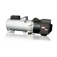
During an electrical test with a digital multimeter, the tem-
perature sensor is to have the values in accordance with the
following graph. The resistance measurement must prefera-
bly be carried out at 20 °C and approx. 100 °C (immerse sen-
sor in water).
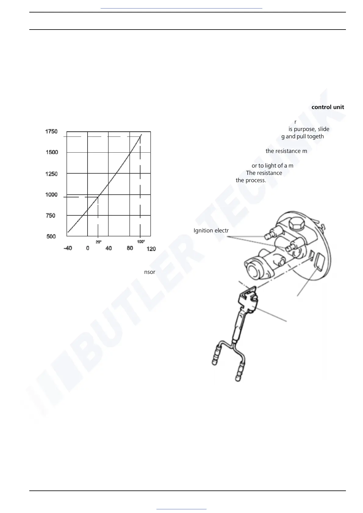
6.3.2 Resistance test of flame monitor
NOTE
The glass element of the flame monitor and the inspection
window of the disc (see illustration) must be cleaned if soiled.
The flame monitor must be replaced if it is damaged or the
setpoint value is not reached.
6.3.2.1 Checking flame monitor with 1553 control unit
– Connect ohmmeter to flame monitor
– Darken flame monitor well. For this purpose, slide on a
piece of black protective sleeving and pull together at the
ends
– After approx. 20 second the resistance must increase to
>100kohms
– Expose flame monitor to light of a match from a distance
of approx. 1 cm. The resistance must drop to approx.
300 ohms in the process.
Fig. 605 Resistance test of temperature sensor
 Loading...


