Service Manual Disassembly and repair 47
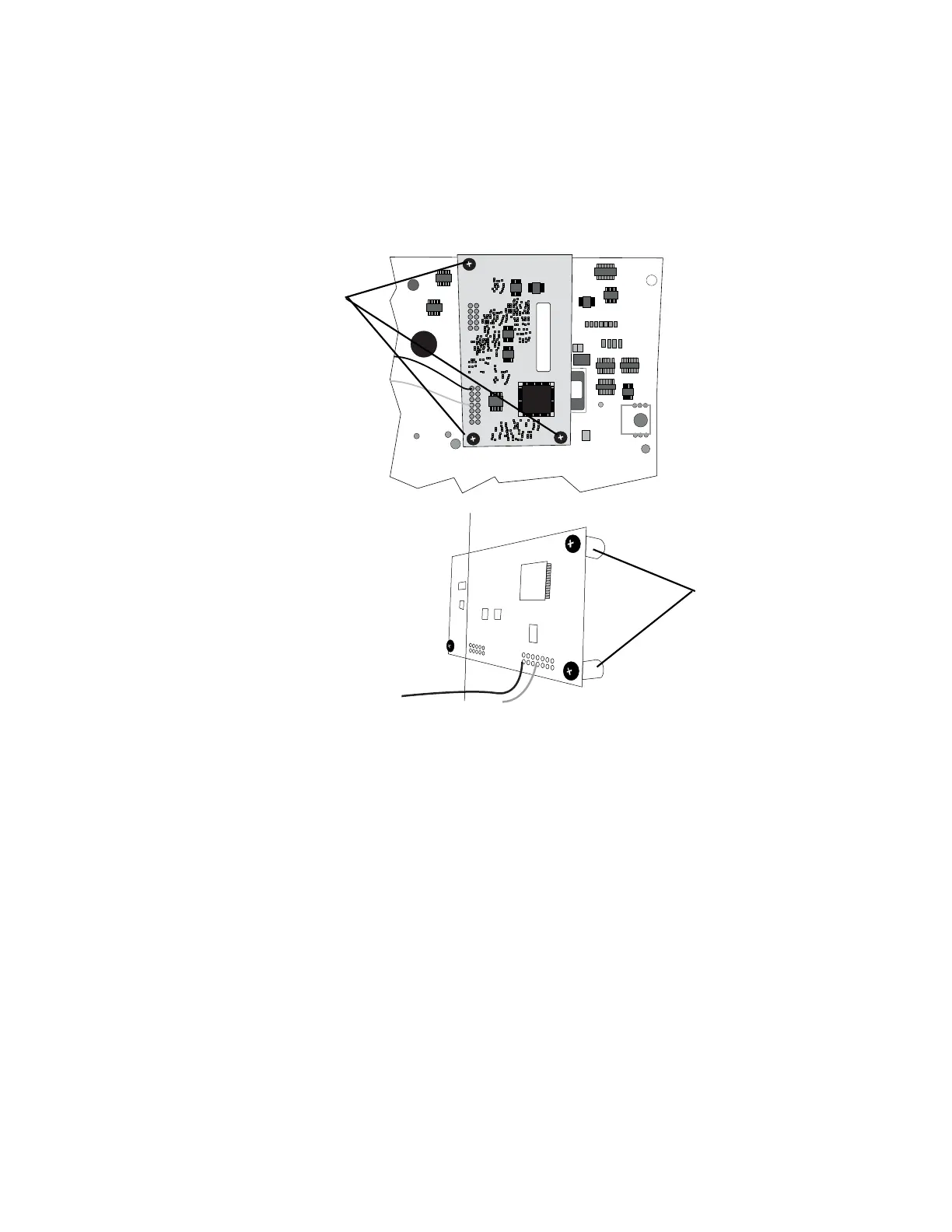
Nellcor board
Follow all the previous steps and then:
1. Remove the three phillips head screws along with the nuts and spacers from the
SpO
2
PCB.
2. Remove the SpO
2
module (Nellcor MP205) from the main PCB.
Note
If a failure occurs in the MP205 PCB (obsolete), update to a Nell-3 PCB (704870)
and update the Main PCB (403290). The new Main PCB (403290) correctly
operates an MP205, an MP506, or a Nell-3 PCB. If the Nell-3 is used with the old
main PCB, an E7 error occurs after connecting the power.
For MP205 PCB: Verify the following:
• There are two shunts at the top of the jumper row on the PCB before
installing on the Main PCB.
• The two locking tabs on the connectors of the Nellcor MP205 PCB are broken
off before installing onto the Main PCB.
• The nylon washers are located on the main PCB when reassembling the
SpO
2
PCB to the Main PCB.
For MP506 or Nell-3 PCB: Verify the following:
• The DIP switch positions are (1-on, 2-on, 3-off and 4-off) on the new PCB and
the two locking tabs on the connectors of the Nellcor MP506 PCB are broken
off before installing onto the Main PCB.
• Verify that the nylon washers are located on the main PCB when
reassembling the SpO
2
PCB to the Main PCB.
Phillips screws
Spacers (3 places)
 Loading...