Main Components and Functions 25
IE
IE
2 Basic Operation
Main Components and Functions
Main Unit
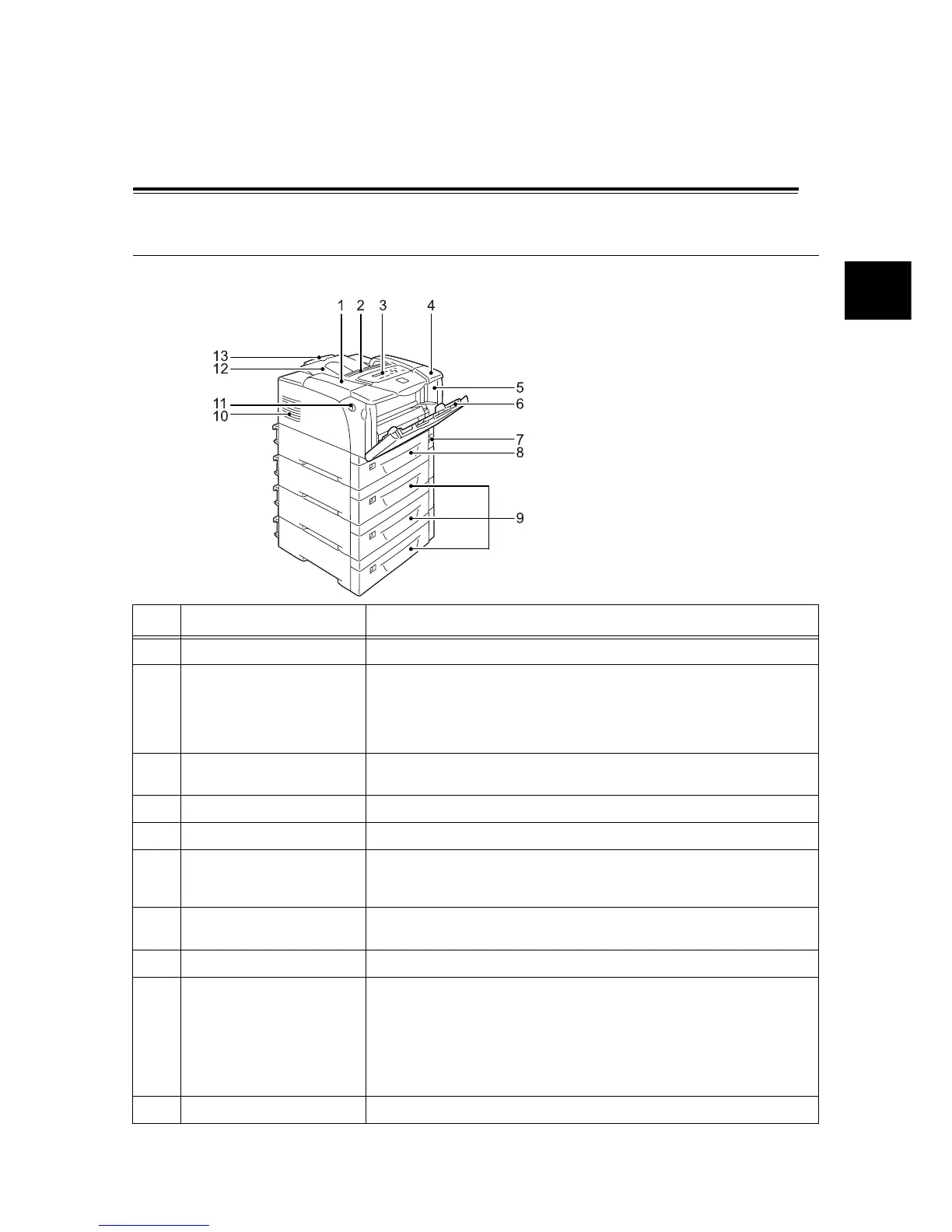
Front/Left View
Note
The illustration on the left is based on the
DocuPrint 3055. The optional tray 4 can be
installed only to the DocuPrint 3055.
No. Name Description
1 Top cover Opened when replacing the print cartridge or clearing paper jams.
2 Ventilation hole Releases heat to prevent the interior of the printer from overheating.
Important
• Do not place any objects on the ventilation hole. Locking the ventilation hole
causes heat build-up in the printer, which causes the printer to malfunction.
3 Control panel Consists of the control buttons, indicator lamps, and a display. For details, refer
to “Control Panel” (P. 28).
4 Upper cover Opened when installing the duplex unit (optional) or cleaning the feed rolls.
5 Front cover Opened when replacing the print cartridge or clearing paper jams.
6 Bypass tray Load paper here when printing using the bypass tray. The bypass tray can
accommodate plain paper and special media such as postcards and
envelopes. It can be extended in two stages as necessary.
7 Power switch Switches the printer on/off. Pressing this to the <|> position switches the power
on, and pressing it to the <O> position switches the power off.
8 Tray 1 Load paper here. This is the standard paper tray.
9 Trays 2, 3, & 4
(250/550 sheet feeders
(optional))
Load paper here when the optional 250/550 sheet feeders (hereinafter referred
to as "sheet feeders") are installed. The above illustration shows the printer with
three sheet feeders (optional).
Note
• The trays 2, 3 and 4 can be added to the DocuPrint 3055.
• The trays 2 and 3 can be added to the DocuPrint 2065.
10 Ventilation hole Releases heat to prevent the interior of the printer from overheating.
 Loading...