AC701 Evaluation Board www.xilinx.com 101
UG952 (v1.3) April 7, 2015
Appendix D
Board Setup
Installing the AC701 Board in a PC Chassis
Installation of the AC701 board inside a computer chassis is required when developing or
testing PCI Express® functionality.
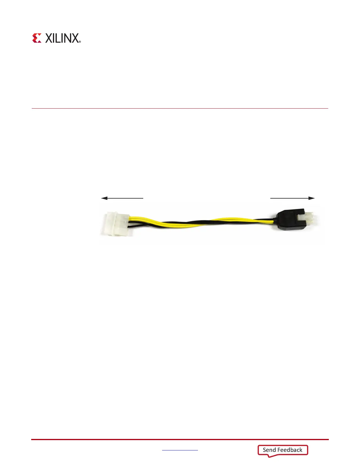
When the AC701 board is used inside a computer chassis (that is, plugged in to the PCIe®
slot), power is provided from the ATX power supply 4-pin peripheral connector through
the ATX adapter cable shown in
Figure D-1 to J49 on the AC701 board. The Xilinx part
number for this cable is 2600304.
To install the AC701 board in a PC chassis:
1. On the AC701 board, remove all six rubber feet, the standoffs, and the PCIe bracket.
The standoffs and feet are affixed to the board by screws on the top side of the board.
Remove all six screws. Reinstall the PCIe bracket using two of the screws.
2. Power down the host computer and remove the power cord from the PC.
3. Open the PC chassis following the instructions provided with the PC.
4. Select a vacant PCIe expansion slot and remove the expansion cover (at the back of the
chassis) by removing the screws on the top and bottom of the cover.
5. Plug the AC701 board into the PCIe connector at this slot.
6. Install the top mounting bracket screw into the PC expansion cover retainer bracket to
secure the AC701 board in its slot.
Note: The AC701 board is taller than standard PCIe cards. Ensure that the height of the card
is free of obstructions.
7. Connect the ATX power supply to the AC701 board using the ATX power supply
adapter cable as shown in
Figure D-1:
a. Plug the 6-pin 2 x 3 Molex connector on the adapter cable into J49 on the AC701
board.
b. Plug the 4-pin 1 x 4 peripheral power connector from the ATX power supply into
the 4-pin adapter cable connector.
X-Ref Target - Figure D-1
Figure D-1: ATX Power Supply Adapter Cable
UG952_c1_34_101612
To ATX 4-Pin Peripheral
Power Connector
To J49 on AC701 Board

 Loading...


