AC701 Evaluation Board www.xilinx.com 43
UG952 (v1.3) April 7, 2015
Feature Descriptions
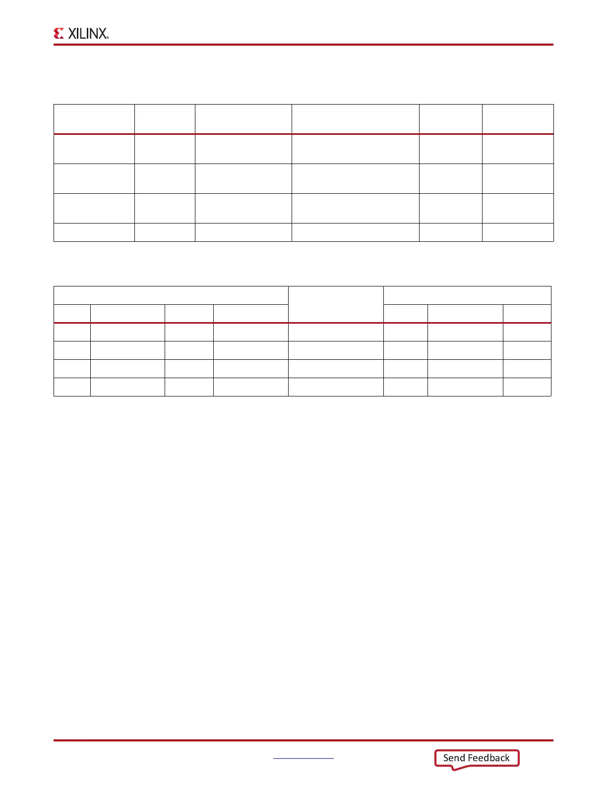
Table 1-17 shows the USB signal definitions at J17.
Table 1-18 shows the USB connections between the FPGA and the UART.
See the Silicon Labs website for technical information on the CP2103GM and the VCP
drivers
[Ref 21].
HDMI Video Output
[Figure 1-2, callout 17]
The AC701 board provides a HDMI video output using the Analog Devices
ADV7511KSTZ-P HDMI transmitter (U48). The HDMI output is provided on a Molex
500254-1927 HDMI type-A connector (P2). The ADV7511 is wired to support 1080P 60
Hz,
YCbCr 4:4:4 encoding using 24-bit input data mapping.
The AC701 board supports the following HDMI device interfaces:
• 24 data lines
• Independent VSYNC, HSYNC
• Single-ended input CLK
• Interrupt Out Pin to FPGA
•I2C
•SPDIF
Table 1-17: USB J17 Mini-B Receptacle Pin Assignments and Signal Definitions
USB Receptacle
Pins (J17)
Receptacle
Pin Name
Schematic
Net Name
Description
U44 Pin
(CP2103GM)
U44 Pin Name
(CP2103GM)
1 VBUS USB_UART_VBUS
+5V from host system - U12
CP2103 power
7, 8 REGIN, VBUS
2 D_N USB_D_N
Bidirectional differential
serial data (N-side)
4 D–
3 D_P USB_D_P
Bidirectional differential
serial data (P-side)
3 D+
4 GND USB_UART_GND Signal ground 2, 29 GND, GND
Table 1-18: FPGA to UART Connections
FPGA (U1)
Schematic Net
Name
CP2103GM Device (U44)
Pin Function Direction IOSTANDARD Pin Function Direction
W19 Request to send Output LVCMOS18 USB_UART_CTS 22 Clear to send Input
V19 Clear to send Input LVCMOS18 USB_UART_RTS 23 Request to send Output
U19 Transmit Data out LVCMOS18 USB_UART_RX 24 Receive data Data in
T19 Receive Data in LVCMOS18 USB_UART_TX 25 Transmit data Data out

 Loading...


