ZC702 Board User Guide www.xilinx.com 23
UG850 (v1.7) March 27, 2019
Feature Descriptions
The USB3320 is clocked by a 24 MHz crystal. Consult the Standard Microsystems
Corporation (SMSC) USB3320 data sheet for clocking mode details [Ref 15].
The interface to the USB3320 transceiver is implemented through the IP in the XC7Z020 SoC
Processor System.
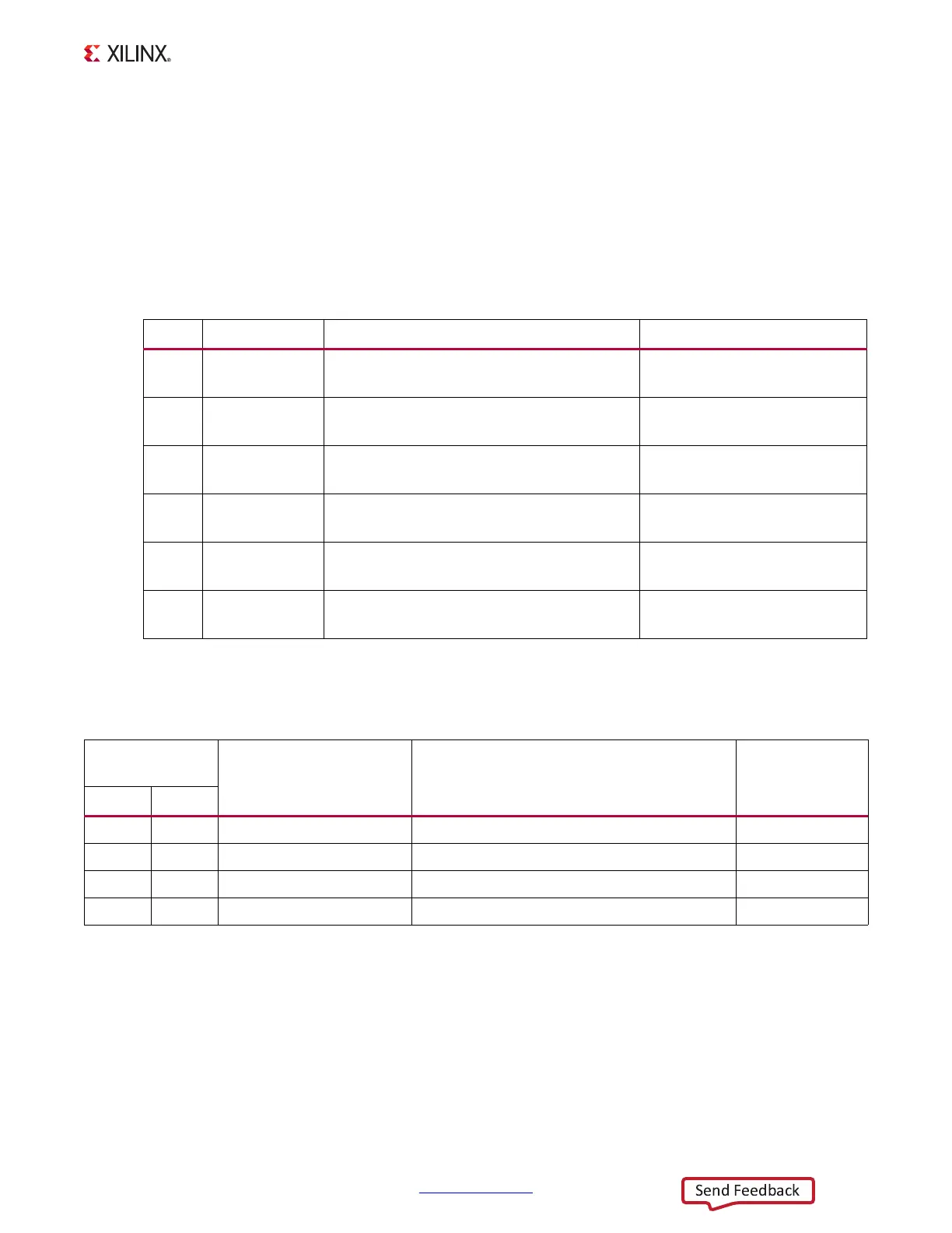
Table 1-6 describes the jumper settings for the USB 2.0 circuit. Bold text identifies the
default shunt positions for USB 2.0 high speed on-the-go (OTG) mode.
The connections between the USB Mini-B connector at J1 and the PHY at U9 are listed in
Table 1-7.
Table 1-6: USB Jumper Settings
Header Function Shunt Position Notes
J44 USB PHY reset Shunt ON = USB PHY reset
Shunt OFF = USB PHY normal operation
Clean reset requires external
debouncing
J7 VBUS 5V
supply
Shunt ON = Host or OTG mode
Shunt OFF = Device mode
J33 RVBUS select Position 1–2 = Device mode (10 k
Ω)
Position 2–3 = OTG mode (1 kΩ)
Overvoltage protection
J35 CVBUS select Position 1-2 = OTG and Device mode (1
μF)
Position 2-3 = Host mode (120 μF)
VBUS load capacitance
J34 Cable ID select Position 1-2 = A/B cable detect
Position 2-3 = ID not used
Used in OTG mode.
J36 USB Micro-B Position 1-2 = Shield connected to GND
Position 2-3 = Shield floating
Table 1-7: USB Connector Pin Assignments and Signal Definitions Between J1 and U9
USB Connector
J1
Net Name Description
USB3320 (U9)
Pin
Pin Name
1 VBUS USB_VBUS_SEL +5V from host system 22
2 D_N USB_D_N Bidirectional differential serial data (N-side) 19
3 D_P USB_D_P Bidirectional differential serial data (P-side) 18
5 GND GND Signal ground 33

 Loading...


