ZC702 Board User Guide www.xilinx.com 42
UG850 (v1.7) March 27, 2019
Feature Descriptions
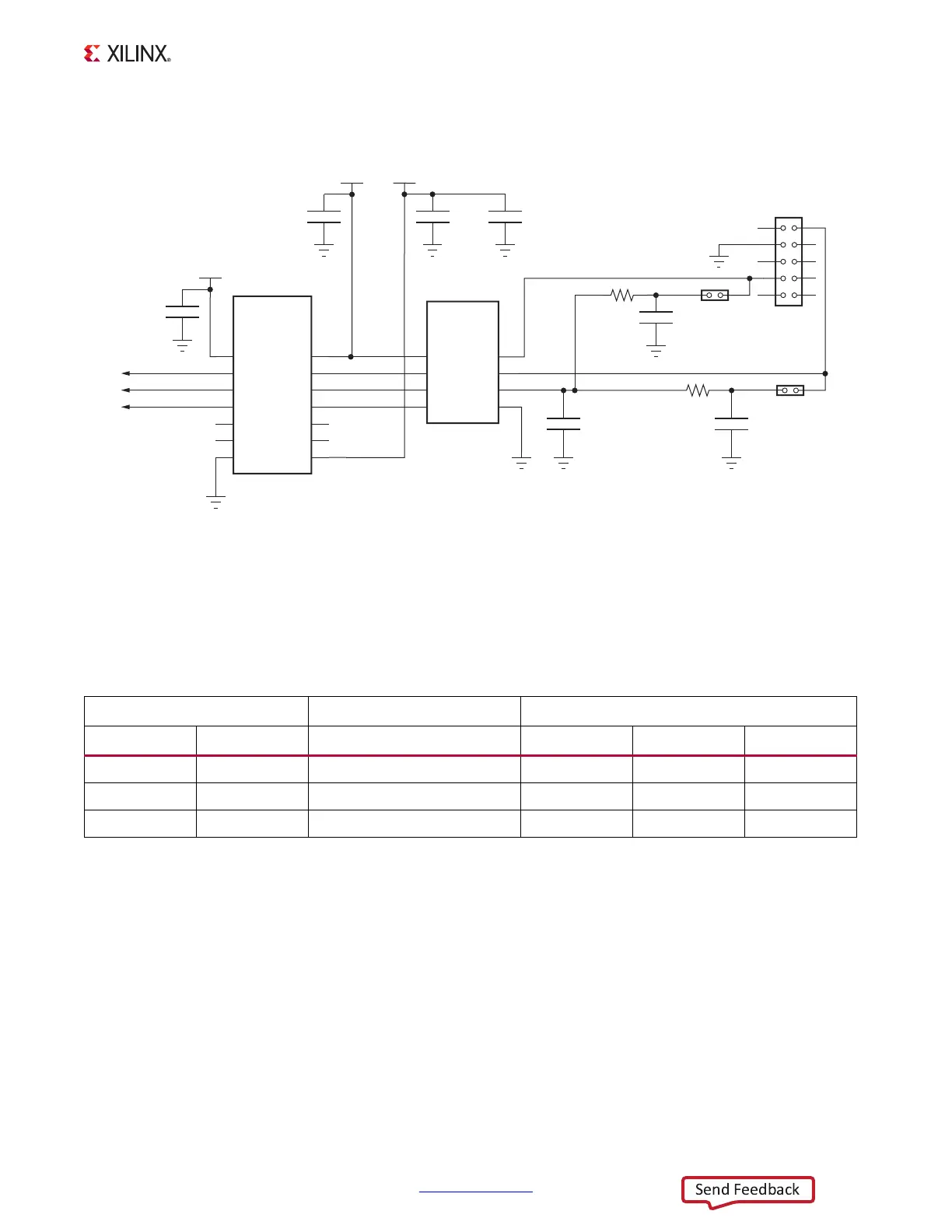
Figure 1-19 shows the controller area network (CAN) bus interface.
Information about the TXS0104E is available at the Texas Instruments website [Ref 25]. Data
sheets and application notes for the TJA01040 CAN transceiver are available at the NXP
Semiconductors website [Ref 24]. Table 1-21 shows the U14 CAN transceiver to U1 XC7Z020
interface connections through level shifter U3.
X-Ref Target - Figure 1-19
Figure 1-19: CAN Bus Interface
VCC5V0
VCCMIO
GND
GND
C26
0.1μF
25V
X5R
GND
C25
0.1μF
25V
X5R
3
1
4
TJA1040
CAN
Transceiver
U14
7
6
5
2
RXD
TXD
VCC
GND
SPLIT
CANL
CANH
8
STB
NC2
B4
OE
1
2
3
TXS0104E
Bidirectional
Voltage-Level
Translator
U3
14
13
12
11
A2
A1
VCCA
B3
B2
B1
VCCB
10
9
8
4
5
6
NC1
A4
A3
7
GND
VCCMIO
GND
C24
0.1μF
25V
X5R
GND
C520
47 μF
10V
X5R
GND
CAN TXD
CAN RXD
CAN STB B
CAN_TXD_LS
CAN_RXD_LS
CAN_STB_B_LS
UG850_c1_19_031913
1
3
5
7
9
2
4
5
8
10
J52
CAN Interface
Connector
CAN_CANH
CAN_CANL
GND
1
2
J15
GND
C304
4700 pF
25V
NPO
GND
C331
18 pF
50V
NPO
R281
60.4Ω
5%
2
1
J53
GND
C330
18 pF
50V
NPO
R282
60.4Ω
5%
Table 1-21: CAN Transceiver SoC Connections
TJA1040 (U14) TXS0104E Level Shifter (U3) XC7Z020 SoC (U1)
Pin Net Name Net Name Low Side Net Bank Pin
1 CAN_TXD CAN_TXD_LS PS_MIO47 501 B10
4 CAN_RXD CAN_RXD_LS PS_MIO46 501 D12
8 CAN_STB_B CAN_STB_B_LS PS_MIO9 500 C4

 Loading...


