EasyManua.ls Logo

Xinje DS2-22P3-AS User Manual

Xinje DS2-22P3-AS
99 pages
To Next Page IconTo Next Page
To Previous Page IconTo Previous Page
Page #71 background imageLoading...
Page #71 background image
63
AB phase feedback signal doesnt have parameters to set; it is motor encoder signal 1:1
output, 2500 pulse/circle.
5-12. I/O signal distribution
5-12-1. Input signal distribution
Parameter range: P5-10~P5-25
Parameter
meaning
Set
value
Meaning
Terminal
voltage
Terminal
state
Signal
state
n.00 y x
00: no meaning
y: 0 always open
1 always close
x: input terminal
no.
n.0000
Not distribute to terminal
input
-
-
0
n.000x
Input always open signal
from SIx
H
Disconnect
to 0V
0
L
Connect to
0V
1
n.0010
Set the signal to be always
valid
-
-
1
n.001x
Input always close signal
from SIx
H
Disconnect
to 0V
1
L
Connect to
0V
0
Note: if the distributed terminal has other signal, set the signal to other terminal or set to unused.
Example: take the input signal /CLR (P5-24) of DS2-21P5-AS as an example to explain
the terminal distribution.
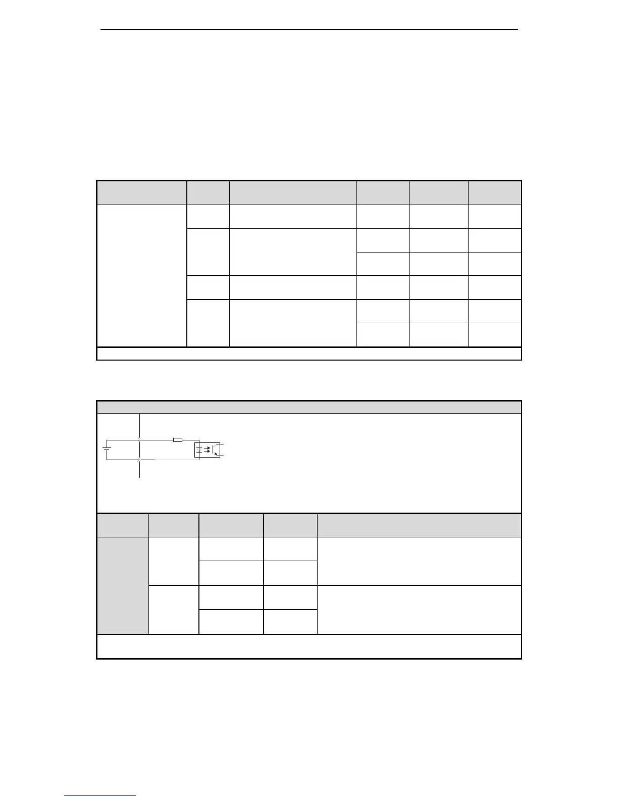
Wiring example of input signal
Parameter
Set value
Terminal
state
Signal
state
Meaning
P5-24
n.0001
Disconnect
to 0V
0
Clear the pulse offset at the moment of SI2 and
0V pass through
Connect to
0V
1
n.0011
Disconnect
to 0V
1
Clear the pulse offset at the moment of SI2 and
0V cut off
Connect to
0V
0
Note: the default input of SI1 is /SON, make sure to distribute P5-10(/SON) to other terminal or set to
unused.
CN0-11
CN0-7
SI1
+24V
3.3KΩ
DS2-21P5-AS: CN0-11 is +24V terminal, CN0-7 is
SI1 terminal. For the example, distribute /CLR signal
to SI1.

Table of Contents

Question and Answer IconNeed help?

Do you have a question about the Xinje DS2-22P3-AS and is the answer not in the manual?

Xinje DS2-22P3-AS Specifications

General IconGeneral
ModelDS2-22P3-AS
CategoryServo Drives
Rated Power2.2kW
Output Current10 A
Control ModePosition, Speed, Torque
Communication InterfaceRS-485, CANopen
Power SupplySingle-phase 220V AC
Protection FeaturesOvercurrent, Overvoltage, Short Circuit

Summary

Safety Precautions

Checking Products upon Delivery

Procedure for checking products upon delivery.

Installation Precautions

Safety guidelines for installing the servo drive and motor.

Wiring Precautions

Safety guidelines for wiring the servo drive and motor.

Operation Precautions

Safety guidelines during servo drive operation.

Checking Product and Part Names

Checking Products on Delivery

Checklist for verifying delivered products.

Installations

Servomotor Installation and Precautions

Covers installation, storage, site, orientation, and handling for servomotors.

Servo Drive Installation and Precautions

Covers storage, site, orientation, and installation for servo drives.

Wiring

Main Circuit Wiring

Details main circuit wiring procedures and terminal arrangements.

Use the Operate Panel

Auxiliary Function

F3-XX Check Alarm Information

List of alarm codes and their descriptions.

Alarm (E-XX)

How alarms are displayed and reset.

Run the Servo System

Control Mode Selection

Describes main and sub modes for servo control.

Basic Function Setting

Parameters for basic servo functions like ON setting and rotation direction.

Speed Control (Analog Voltage Command)

How to control speed using analog voltage input.

Speed Control (Internal Speed)

How to control speed using internal settings.

Speed Control (Pulse Frequency Command)

How to control speed using pulse frequency commands.

Torque Control (Analog Voltage Command)

How to control torque using analog voltage input.

Servo Gain Adjustment

Alarm Information

Alarm Code Descriptions

List of alarm codes, reasons, and solutions.

Appendix 1 Parameter List

Related product manuals