Home
Xinje
Servo Drives
DS2-22P3-AS
Xinje DS2-22P3-AS User Manual
5
of 1
of 1 rating
99 pages
Give review
Manual
Specs
To Next Page
To Next Page
To Previous Page
To Previous Page
Loading...
72
MS
-130ST-M06025
□□
-21
P5
MS
-130ST-M10015
□□
-21
P5
MS
-130ST-M06025
□□
-41
P5
MS-130ST-M10015
□□
-41
P5
MS
-130ST-M15015
□□
-22
P3
MS-180ST-M19015
□□
-
4
3
P0
MS
-
130
ST
-
M1
0030
□□
-43
P0
MS
-180ST-M
20015
□□
-43
P0
7
-
1
-
3
.
Servo motor dim
ensions
Dimensions of
60
series servo motors (unit:
mm
)
79
81
Table of Contents
Default Chapter
5
Table of Contents
5
Preface
9
1 Checking Product and Part Names
10
Checking Products on Delivery
10
Product Appearance and Name Rule
10
Adaptation Table of Servo Drive and Motor
13
2 Installations
14
Servomotor
14
Storage Temperature
14
Installation Site
14
Concentricity
14
Orientation
15
Handling Oil and Water
15
Cable Stress
15
Servo Drive
15
Storage Conditions
15
Installation Site
15
Orientation
16
Installation
16
3 Wiring
18
Main Circuit Wiring
18
The Terminal Arrangement
18
Main Circuit Terminals
19
Winding Terminals on Servo Motor
21
CN0, CN1, CN2 Terminals
21
Communication Port
23
Signal Terminals
24
Pulse Signal
24
SI Input Signal
25
Analog Input Circuit
26
Output Signal
26
Encoder Feedback Signal
27
Standard Wiring Example
27
Position Control Mode
27
Regenerative Resistor
31
4 Use the Operate Panel
32
Basic Operation
32
Functions of Operate Panel
32
Basic Mode Switching
32
Running Status Mode
33
Monitoring Mode
34
Auxiliary Function
36
F0-XX
36
F1-XX
36
Change the Motor Type (F2-00)
37
Check Alarm Information (F3-XX)
38
Reset Parameters to Default (F4-XX)
38
External Monitoring (F5-XX)
38
Alarm (E-XX)
38
Example
38
5 Run the Servo System
40
Control Mode Selection
40
Basic Function Setting
40
Servo on Setting
41
Switch the Motor Rotate Direction
41
Motor Stop Mode When Use Overtravel Signal
41
Overtravel Limit (P-OT & N-OT)
42
Power-Off Brake (BK)
43
Alarm Output
44
Running Time
45
Torque Over-Limit
45
Position Mode (External Pulse Command)
45
Control Mode Selection
46
Pulse Command
46
Electronic Gear Ratio
47
Position Command Filter
48
Pulse Error Clear (/CLR)
49
Positioning Complete (/COIN)
49
Positioning Near (/NEAR)
50
Command Pulse Prohibition (/INHIBIT)
50
Position Mode (Internal Position Mode)
51
Control Mode Selection
51
Internal Position Mode
51
Position Parameters from Segment 1 to 16
54
Change Step (/CHGSTP)
54
Pause Current Signal (/INHIBIT)
54
Skip Current Signal (/ZCLAMP)
55
Reference Origin
55
Set Segment through Communication
57
Speed Control (Analog Voltage Command)
57
Control Mode Selection
57
Analog Value of Rated Speed
58
Speed Command Offset Auto-Adjustment (F1-03)
58
Proportion Action Command (/P-CON)
58
Zero Clamp (/ZCLAMP)
58
Speed Coincidence Checking (/V-CMP)
59
Torque Limit
59
Internal Torque Limit (Output Torque Max Value Limit)
59
External Torque Limit (Via Input Signal)
59
External Torque Limit (Via Analog Voltage Command)
60
External Torque Limit (Via External Input + Analog Voltage)
60
Output Torque up to Limit Value Signal
61
Soft Start
61
Filter
62
Speed Command Input Dead Voltage
62
Speed Control (Internal Speed)
62
Control Mode Selection
63
Internal Speed Setting
63
Input Signal Setting
64
Speed Control (Pulse Frequency Command)
65
Control Mode Selection
65
Pulse Frequency Command
65
Command Pulse Frequency at Rated Speed
65
Speed Command Pulse Filter Time
66
Torque Control (Analog Voltage Command)
66
Control Mode Selection
66
The Analog Value of Rated Torque
66
Torque Command Offset Autoadjustment (F1-04)
67
Torque Command Filter Time
67
Torque Limit
67
Internal Speed Limit
67
External Speed Limit
67
Speed up to Limit Value Output
68
Torque Command Input Dead Area Voltage
68
Torque Control (Internal Setting)
68
Control Mode Selection
68
Internal Torque Command
68
Switch the Control Mode
69
Other Output Signals
69
ALM and /ALM-RST
69
Warn
69
Rotation Checking (/TGON)
69
Servo Ready (/S-RDY)
70
Encoder Z Phase Output (/Z)
70
AB Phase Feedback Signal of Encoder
70
I/O Signal Distribution
71
Input Signal Distribution
71
Default Setting of Input Terminal
72
Output Terminal Distribution
72
Default Setting of Output Terminal
72
6 Servo Gain Adjustment
73
Gain Setting of Speed Loop
73
Gain Setting of Position Loop
73
The Experience of Parameter Adjustment
74
Proportion Action Command (P-CON)
74
Gain Switch (G-SEL)
75
7 Specification and Dimension
76
Servo Motor
76
Servo Motor Specification
76
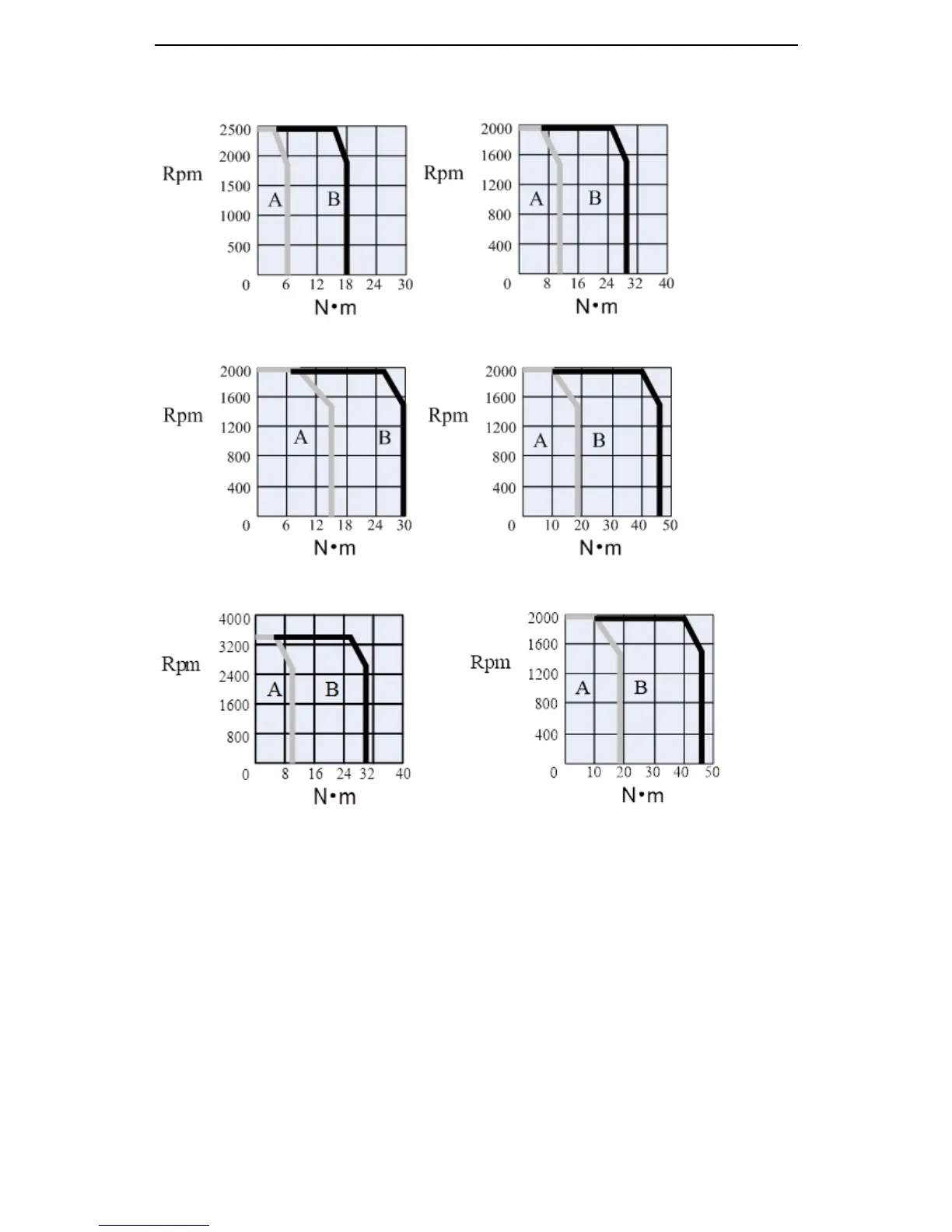
Torque-Speed Feature
79
Servo Motor Dimensions
80
Servo Drives
84
General Specification
84
Performance Specification
84
Servo Drive Dimensions
85
8 Alarm Information
88
Appendix 1 Parameter List
90
5
Based on 1 rating
Ask a question
Give review
Questions and Answers:
Need help?
Do you have a question about the Xinje DS2-22P3-AS and is the answer not in the manual?
Ask a question
Xinje DS2-22P3-AS Specifications
General
Brand
Xinje
Model
DS2-22P3-AS
Category
Servo Drives
Language
English
Related product manuals
Xinje DS2-21P5-AS
99 pages
Xinje DS2-20P7-BSW
99 pages
Xinje DS2 series
98 pages
Xinje DS2-43P0-AS
99 pages
Xinje DS2-41P5-AS
99 pages
Xinje DS3 Series
152 pages
Xinje DS5F Series
210 pages
Xinje DS5C Series
121 pages
Xinje DS5L1 Series
171 pages
Xinje DS5F-21P5-PTA
210 pages
Xinje DS5F-43P0-PTA
210 pages
Xinje DS3 series servo
41 pages
 Loading...


