Page 12
F
T-991
OperaTing Manual
before You beGin
grounding
The
FT-991
transceiver, like any other HF communications apparatus, requires an effective ground system for maxi-
mum electrical safety and best communications effectiveness. A good ground system can contribute to station efciency
in a number of ways:
It can minimize the possibility of electrical shock to the operator.
It can minimize RF currents owing on the shield of the coaxial cable and the chassis of the transceiver. Such cur-
rents may lead to radiation, which can cause interference to home entertainment devices or laboratory test equip-
ment.
It can minimize the possibility of erratic transceiver/accessory operation caused by RF feedback and/or improper
current ow through logic devices.
An effective earth ground system may take several forms. For a more complete discussion, see an appropriate RF engi-
neering text. The information below is intended only as a guideline.
Typically, the ground connection consists of one or more copper-clad steel rods, driven into the ground. If multiple
ground rods are used, they should be positioned in a “V” conguration and bonded together at the base of the “V” which
is nearest the station location. Use a heavy, braided cable (such as the discarded shield from type RG-213 coaxial cable)
and strong cable clamps to secure the braided cable(s) to the ground rods. Be sure to weatherproof the connections
to ensure many years of reliable service. Use the same type of heavy, braided cable for the connections to the station
ground bus (described below).
Inside the station, a common ground bus consisting of a copper pipe of at least 25 mm diameter should be used. An al-
ternative station ground bus may consist of a wide copper plate (single-sided circuit board material is ideal) secured to
the bottom of the operating desk. Grounding connections from individual transceivers, power supplies, and data com-
munications devices (TNCs, etc.) should be made directly to the ground bus using a heavy, braided cable.
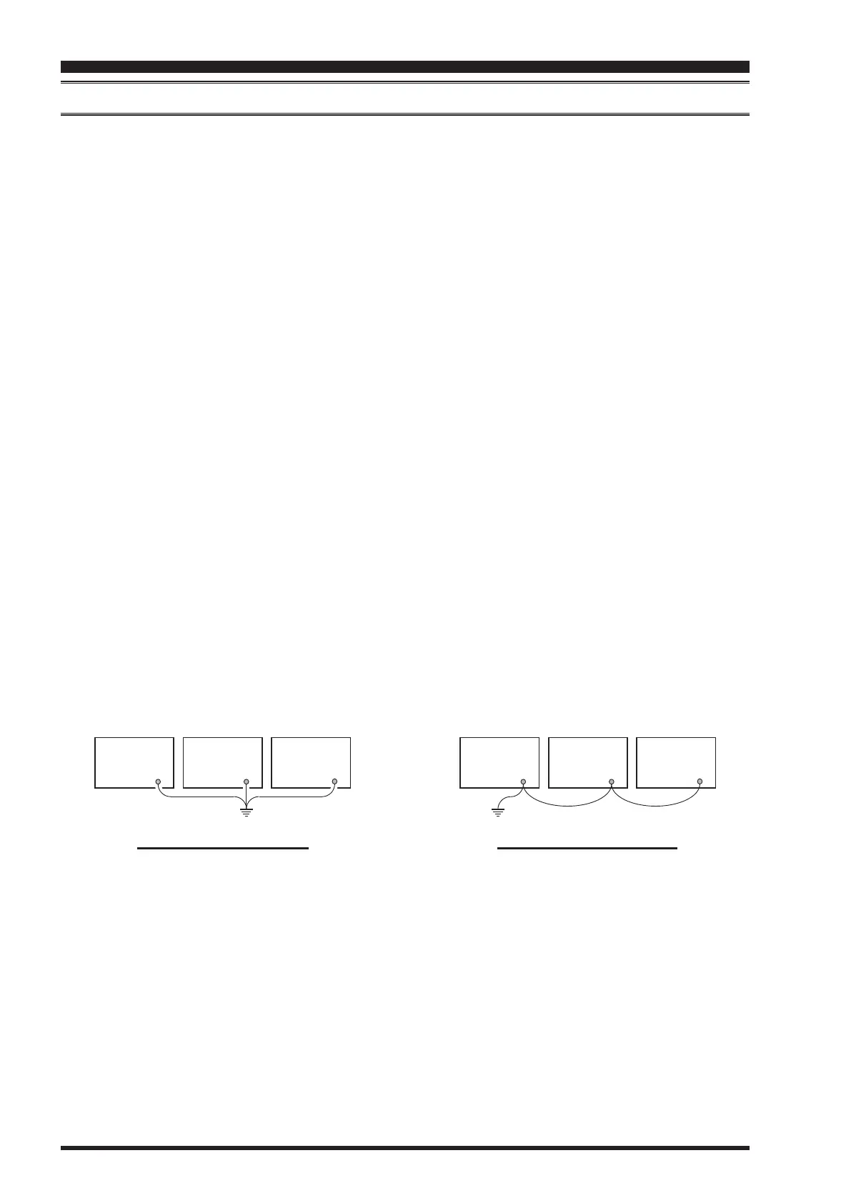
Do not “Daisy-Chain” ground connections from one electrical device to another and thence to the ground bus. This
method may nullify any attempt at effective radio frequency grounding. See the drawing below for examples of proper
grounding techniques.
Inspect the ground system - inside the station as well as outside - on a regular basis to ensure continued performance
and safety.
Besides following the above guidelines carefully, note that household or industrial gas lines must never be used in an
attempt to establish an electrical ground. Cold water pipes may, in some instances, help in the grounding effort, but gas
lines represent a signicant explosion hazard, and must never be used.
proper ground connection
GND
Linear
Amplifier
GND
TNC
GND
Transceiver
GND
Transceiver
GND
Linear
Amplifier
GND
TNC
"Daisy Chain"
GND
Linear
Amplifier
GND
TNC
GND
Transceiver
GND
Transceiver
GND
Linear
Amplifier
GND
TNC
"Daisy Chain"
iMproper ground connection
 Loading...