Page 25
F
T-991
OperaTing Manual
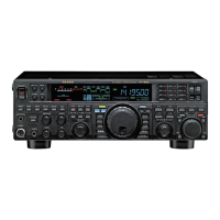
rear panel
GND
Use this terminal to connect the transceiver to a good
earth ground, for safety and optimum performance.
Use a large diameter, short braided cable to make
the ground connections. For details on grounding the
transceiver, see “Grounding” on page 12.
ANT Jack (144/430MHz)
This is the M-type coaxial connector for the 144
MHz band and 430 MHz band antennas (50 ohms).
RTTY/DATA Jack
This is the input/output jack to connect a terminal
unit for RTTY and TNC for packet communications.
DATA IN
GND
DAKY
SHIFT
RTYO
BUSY
TUN/LIN Jack
Connect the optional external antenna tuner “
FC-40
”
or the linear amplier “
VL-1000
”.
+13V OUT
TX GND
GND
TX D (BAND A)
RX D (BAND B)
BAND C
RESET (BAND D)
TX INH
GPS/CAT Jack
This is the
RS-232C
jack for connecting a computer
or a commercially available external GPS device.
This is the
RS-232C
jack for connecting a comput-
er.
Connecting a computer to this jack, using a com-
mercially available
RS-232C
straight cable, enables
CAT control of the transceiver.
① DCD
② SERIAL OUT/RXD
(GPS DATA IN)
③ SERIAL IN
④ DTR
⑤ GND
⑥ DSR
⑦ RTS
⑧ CTS
⑨ RI
①②③④⑤
⑧⑨ ⑦ ⑥
DC IN Jack
This is the DC power supply connection for the
transceiver. Use the supplied DC cable to connect di-
rectly to a DC power supply, which must be capable
of supplying at least 23 A @13.8 VDC.
43
2
1
5
7 8
6
9
11
10
 Loading...