7-14
Power unit assembly
0
1
2
3
4
5
6
7
8
9
10
A
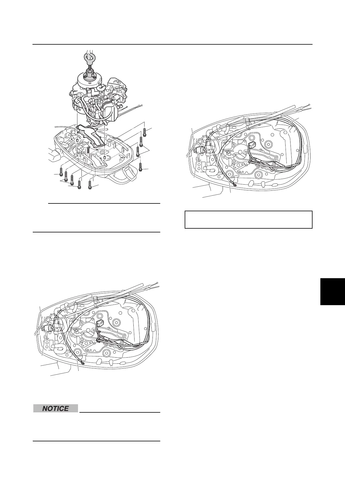
Lift up the power unit using the crane,
because the gasket on power unit is firmly
adhered to the upper case.
17. Loosen the engine shut-off switch nut D,
and then remove the engine shut-off
switch E and ground lead j from the
bottom cowling.
Installing the power unit
Do not turn the flywheel magnet counter-
clockwise. Otherwise, the water pump
impeller could be damaged.
1. Install the engine shut-off switch a, and
then tighten the engine shut-off switch
nut b to the specified torque.
2. Route the engine shut-off switch lead a
and ground lead c.
3. Install the special service tool. See steps
13–15 in “Removing the power unit” (7-
12).
4. Clean the power unit mating surface, and
then install the dowels d and a new
gasket e. NOTICE: Do not reuse a
gasket, always replace it with a new
one.
5. Install the power unit, and then tighten
the power unit mounting bolts f and g
to the specified torque in the order a, b,
and so on.
j
E
D
Engine shut-off switch nut b:
2 N·m (0.2 kgf·m, 1.5 ft·lb)
c
a
b
a
 Loading...