8-15
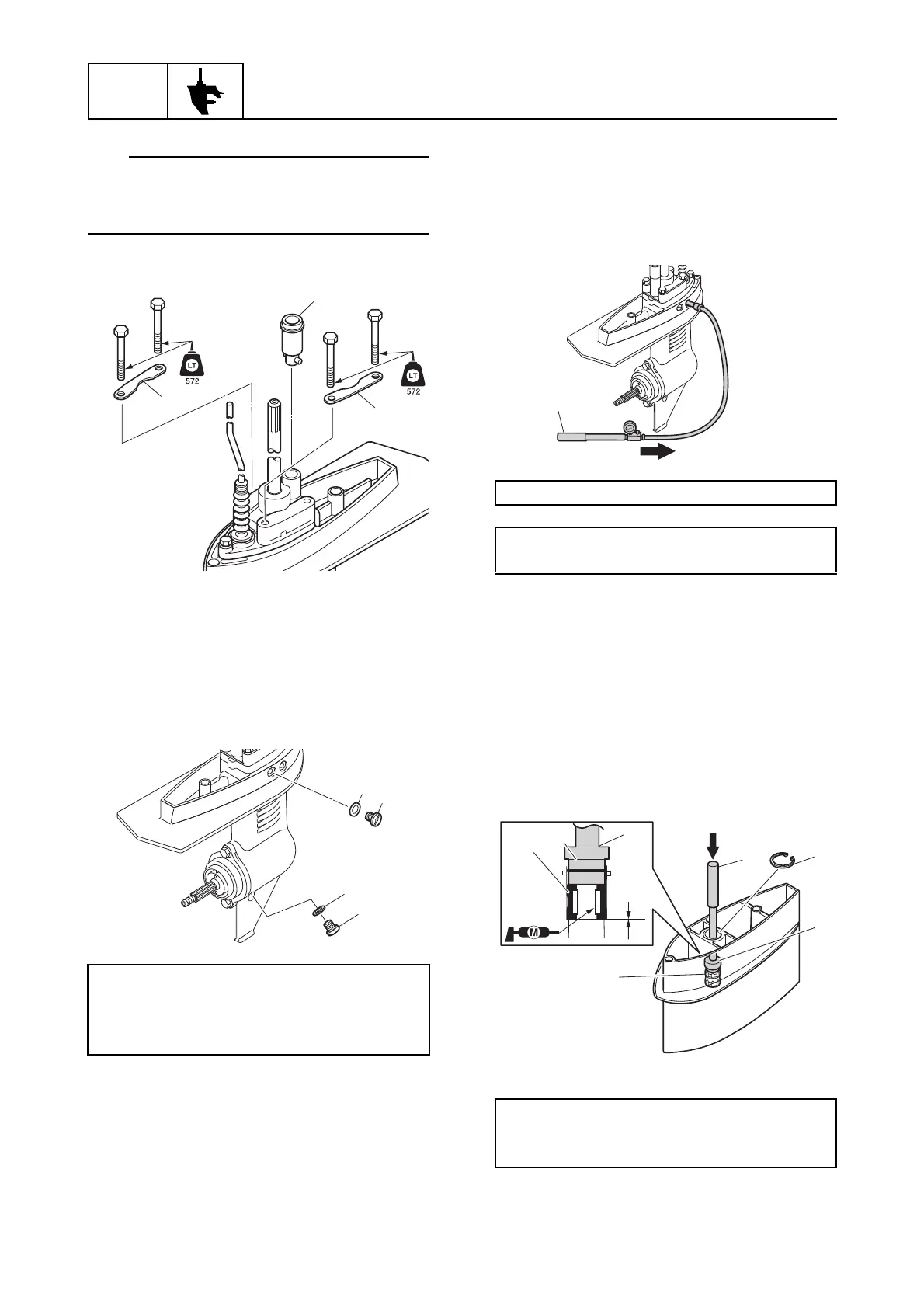
Lower unit
While turning the drive shaft clockwise, push
down on the water pump housing and install
water pump housing.
8. Install the plates m and rubber seal n.
Checking the lower unit for air
leakage
1. Install new gaskets a, the drain screw b
and the flushing screw c.
2. Tighten the drain screw b and flushing
screw c to the specified torque.
3. Install the special service tool d.
4. Apply the specified pressure to check
that the pressure is maintained in the
lower unit for at least 10 seconds.
NOTICE: Do not over pressurize the
lower unit. Otherwise, the oil seals
could be damaged.
5. If the specified pressure cannot be
maintained, check the drive shaft,
propeller shaft, and rubber seal for bends
or damage, and check the shift rod
rubber seal for damage or wear.
Assembling the extension (L-
transom model)
1. Install the bushing a and circlip b.
Drain screw b:
9 N·m (0.9 kgf·m, 6.6 ft·lb)
Flushing screw c:
9 N·m (0.9 kgf·m, 6.6 ft·lb)
n
m
m
Leakage tester d: 90890-06840
Holding pressure:
98.0 kPa (0.98 kgf/cm
2
, 14.2 psi)
Driver rod L3 c: 90890-06652
Needle bearing attachment d:
90890-06615
d
 Loading...