1-11
Specification
Bracket unit
General tightening torque
This chart indicates the tightening torques for
standard fasteners with a standard ISO
thread pitch. Tightening torque specifications
for special components and assemblies are
provided in the applicable sections of this
manual. To prevent warpage, tighten multi-
fastener assemblies in a crisscross fashion
and progressive stages until the specified
torque is reached. Unless otherwise indi-
cated, torque specifications require clean,
dry threads.
Components should be at room temperature.
Part to be tightened Screw size
Tightening torques
N·m kgf·m ft·lb
Throttle rod screw M5 4 0.4 3.0
Throttle grip screw M5 4 0.4 3.0
Tiller handle mounting bolt M8 28 2.8 20.7
Carrying handle bolt M8 19 1.9 14.0
Start-in-gear protection cable locknut — 4 0.4 3.0
Primer pump holder bolt M6 11 1.1 8.1
Shift lever bolt M8 19 1.9 14.0
Shift link bolt M5 3.5 0.35 2.58
Grease nipple — 3 0.3 2.2
Self-locking nut — 15 1.5 11.1
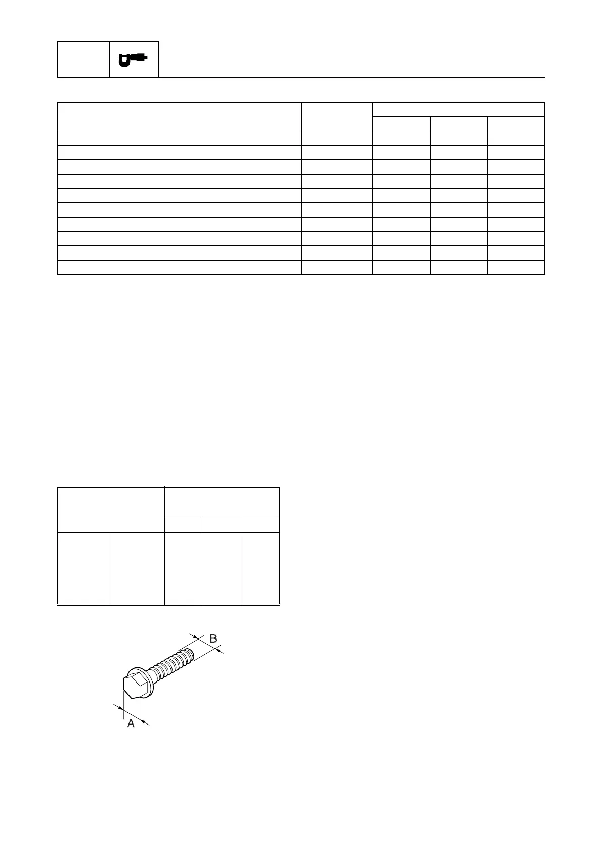
Width
across
flats (A)
Screw
size (B)
General torque
specifications
N·m kgf·m ft·lb
8mm
10 mm
12 mm
14 mm
17 mm
M5
M6
M8
M10
M12
5
8
18
36
43
0.5
0.8
1.8
3.6
4.3
3.7
5.9
13.3
26.6
31.7

 Loading...