7-32
Cylinder head
0
1
2
3
4
5
6
7
8
9
10
A
2. Calculate the valve guide clearance.
Replace the valve guide if out of
specification.
Replacing the valve guide
After replacing the valve guide, check the
valve seat contact area.
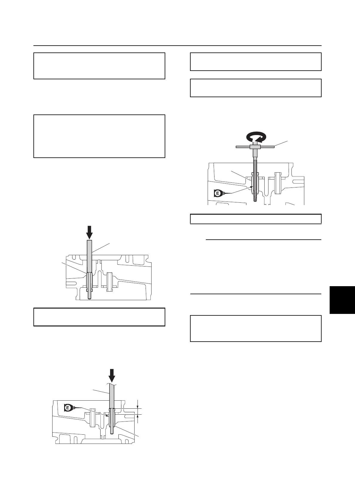
1. Remove the valve guide a from the com-
bustion chamber side using the special
service tool b.
2. Install a new valve guide c from the
rocker arm side to the specified
installation height a using the special
service tool b.
3. Insert the special service tool d into the
valve guide c, and then ream the valve
guide.
• Turn the valve guide reamer clockwise to
ream the valve guide.
• Do not turn the valve guide reamer counter-
clockwise when removing it.
• Make sure to clean the valve guide after
reaming it.
4. Measure the valve guide inside diameter.
Checking the valve seat
1. Remove carbon deposits from the valves.
2. Apply a thin, even layer of Mechanic's
blueing dye (Dykem) onto the valve seat.
3. Press the valve lightly against the valve
seat using the special service tool a.
Valve guide inside diameter a:
Intake and exhaust:
5.500–5.512 mm (0.2165–0.2170 in)
Valve guide clearance:
Intake:
0.010–0.037 mm (0.0004–0.0015 in)
Exhaust:
0.025–0.052 mm (0.0010–0.0020 in)
Valve guide remover/installer b:
90890-06801
b
a
a
b
c
Valve guide remover/installer b :
90890-06801
Valve guide installation height a:
8.2–9.1 mm (0.32–0.36 in)
Valve guide reamer d: 90890-06804
Valve guide inside diameter:
Intake and exhaust:
5.500–5.512 mm (0.2165–0.2170 in)
d
c