7-44
Cylinder block
0
1
2
3
4
5
6
7
8
9
10
A
Do not place the Plastigauge (PG-1) over the
oil hole in the crankpin of the crankshaft.
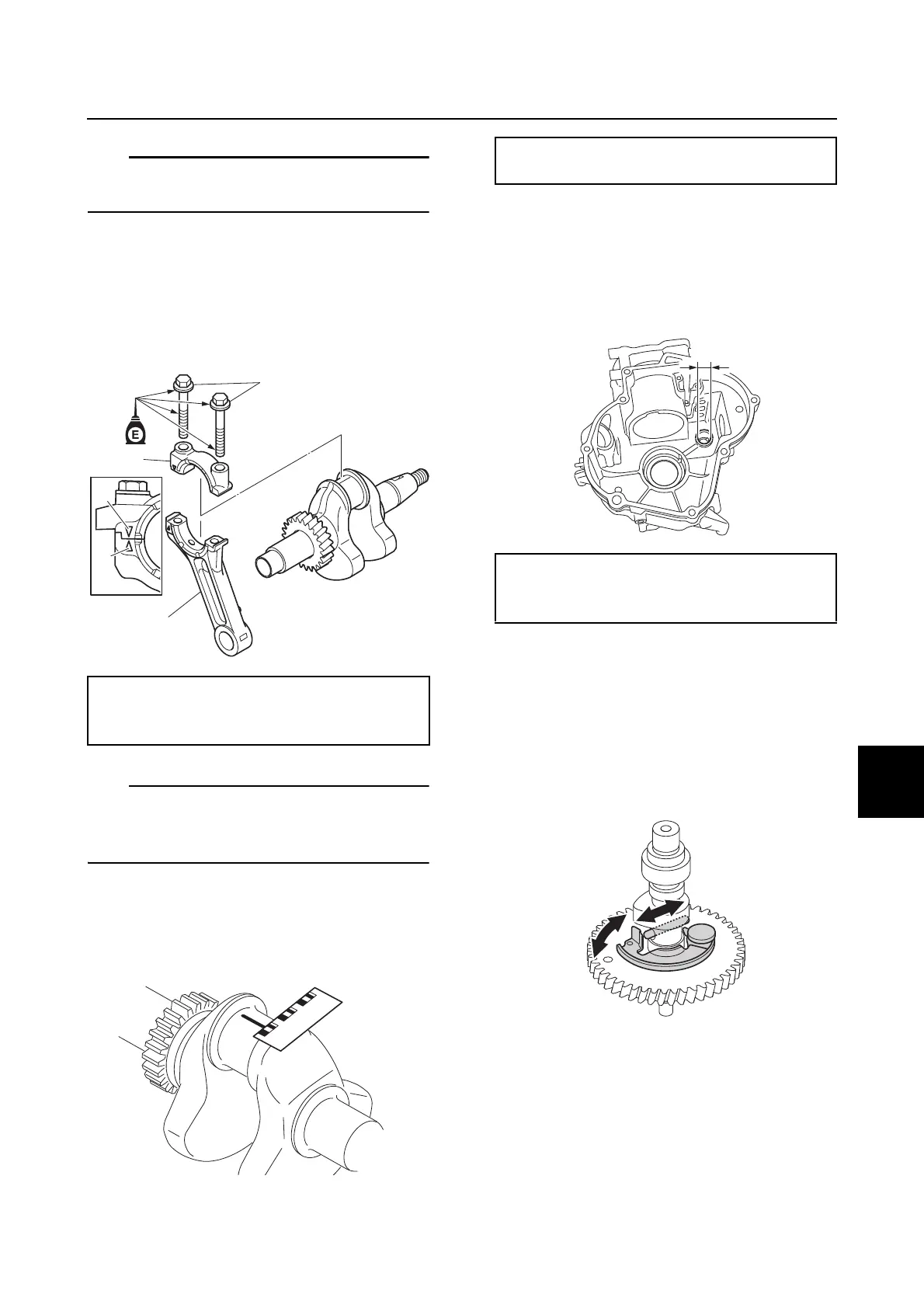
3. Install the connecting rod cap b by
aligning the mark c on the connecting
rod d and the mark e on the connecting
rod cap b, and then tighten the
connecting rod cap bolts a to the
specified torques in 2 stages.
Do not turn the connecting rod until the con-
necting rod oil clearance measurement has
been completed.
4. Remove the connecting rod cap, and
then measure the width of the
compressed Plastigauge (PG-1) on the
crankpin.
Checking the cylinder block
1. Check the cylinder block. Replace if cor-
roded or cracked.
2. Measure the camshaft journal inside
diameter a.
Checking the camshaft
1. Check the camshaft gear. Replace the
camshaft if damaged or worn.
2. Check the decompression actuator.
Replace the camshaft if the
decompression actuator does not
operate smoothly.
3. Measure the cam lobe height a, cam
lobe width b, and fuel pump cam
diameter c.
Connecting rod cap bolt a:
1st: 6 N·m (0.6 kgf·m, 4.4 ft·lb)
2nd: 12 N·m (1.2 kgf·m, 8.9 ft·lb)
Connecting rod oil clearance:
0.016–0.046 mm (0.0006–0.0018 in)
Camshaft journal inside diameter a:
15.000–15.018 mm
(0.5906–0.5913 in)
 Loading...