7-42
Cylinder block
0
1
2
3
4
5
6
7
8
9
10
A
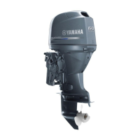
Checking the piston ring groove
1. Measure the piston ring grooves.
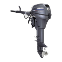
Checking the piston ring side
clearance
1. Measure the piston ring side clearance.
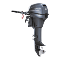
Checking the piston pin boss inside
diameter
1. Measure the piston pin boss inside diam-
eter a.
Do not measure it at the groove b.
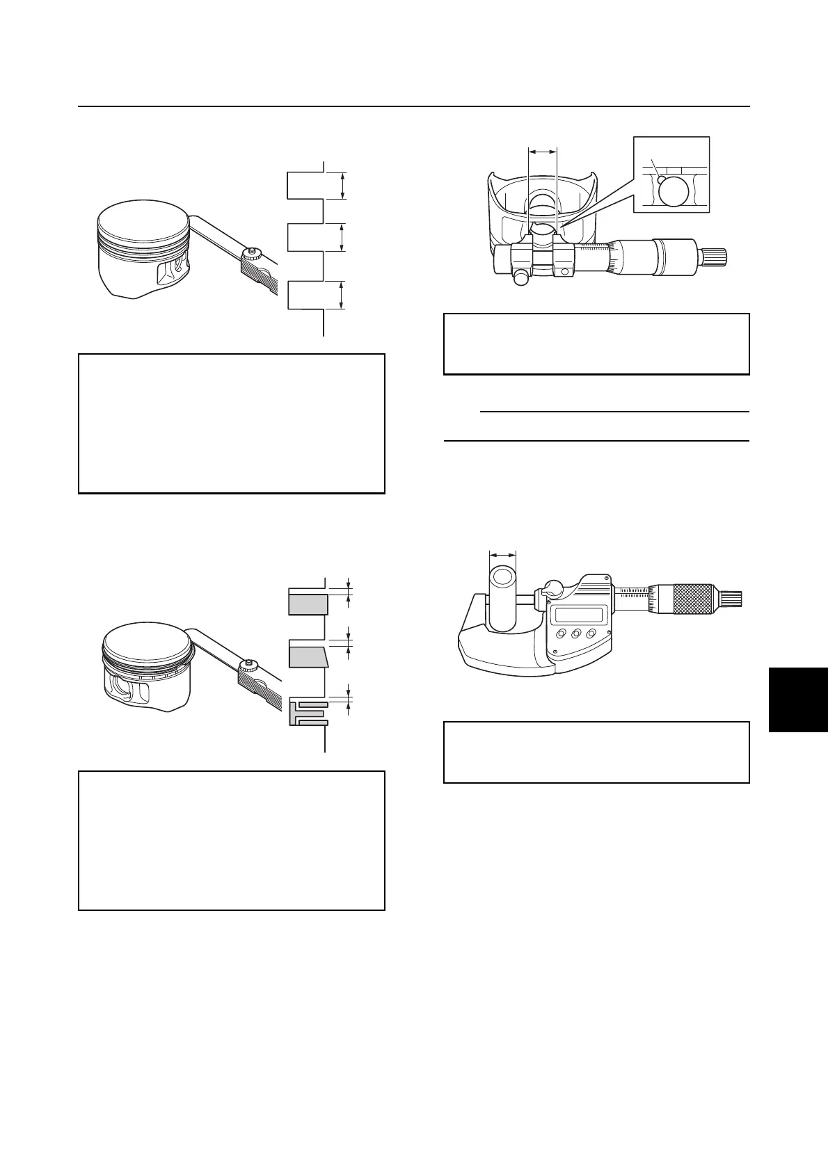
Checking the piston pin diameter
1. Measure the piston pin outside diameter
a.
Checking the connecting rod small
end inside diameter and big end
inside diameter
1. Install the connecting rod cap a by align-
ing the mark b on the connecting rod c
and the mark d on the connecting rod
cap a, and then tighten the connecting
rod cap bolts a to the specified torques
in 2 stages.
2. Measure the connecting rod small end
inside diameter e and the big end inside
diameter f.
Piston ring groove:
Top ring a:
1.210–1.230 mm (0.0476–0.0484 in)
2nd ring b:
1.210–1.230 mm (0.0476–0.0484 in)
Oil ring c:
2.010–2.030 mm (0.0791–0.0799 in)
Piston ring side clearance:
Top ring a:
0.020–0.060 mm (0.0008–0.0024 in)
2nd ring b:
0.020–0.060 mm (0.0008–0.0024 in)
Oil ring c:
0.010–0.180 mm (0.0004–0.0071 in)
a
b
c
a
b
c
Piston pin boss inside diameter a:
15.004–15.015 mm
(0.5907–0.5911 in)
Piston pin outside diameter a:
14.995–15.000 mm
(0.5904–0.5906 in)
a
b
a
 Loading...