5-4
Charging unit and component
0
1
2
3
4
5
6
7
8
9
10
A
Charging unit and component
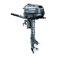
Checking the lighting coil (optional
for European market)
1. Remove the holder a, and then discon-
nect the lighting coil connectors a.
2. Measure the lighting coil output peak
voltage.
To prevent the engine from starting when
cranking it, remove the clip from the engine
shut-off switch.
3. Measure the lighting coil resistance.
4. Connect the lighting coil connectors, and
then fasten the lighting coil leads using
the holder a.
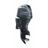
Checking the Rectifier Regulator
(optional for European market)
If the battery cables are connected in
reverse, the Rectifier Regulator can be
damaged.
1. Remove the holder a.
2. Measure the Rectifier Regulator output
peak voltage.
Do not use peak voltage adapter B when
measuring the Rectifier Regulator output
peak voltage.
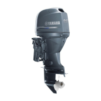
3. Disconnect the Rectifier Regulator
connectors a, b, c, and Rectifier
Regulator ground lead d.
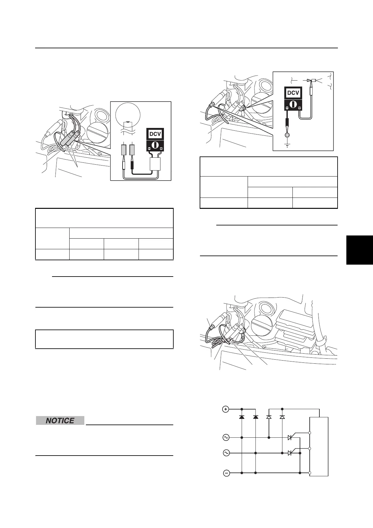
4. Check the Rectifier Regulator for
continuity. Replace if out of specification.
Lighting coil output peak voltage:
Green (G)–Green (G)
r/min
Unloaded
Cranking 1500 3500
DC V 20.0 30.1 64.3
Lighting coil resistance (reference data):
0.771–0.869 at 20 °C (68 °F)
Rectifier Regulator peak voltage:
Red (R)–Ground
r/min
Loaded
1500 3500
DC V 13.0 13.0
a
b
c
d
Checking the electrical component / Charging unit and component

 Loading...