5-3
Electrical system
Checking the electrical
component
Measuring the peak voltage
When measuring the peak voltage, do not
touch any of the connections of the digital
tester probes.
When measuring the peak voltage
between the terminals of an electrical
component using the digital tester, make
sure that the leads do not contact any
metal parts. Otherwise, the electrical com-
ponent may short-circuit and be dam-
aged.
To check the electrical components or mea-
sure the peak voltage, use the special ser-
vice tools. A malfunctioning electrical
component can be checked easily by mea-
suring the peak voltage. The specified engine
speed when measuring the peak voltage is
affected by many factors, such as fouled
spark plugs or a weak battery. If one of these
factors is present, the peak voltage cannot be
measured properly.
• Before measuring the peak voltage, check
all wiring harness for corrosion. Also, make
sure that the wiring harness is connected
properly and that the battery is fully
charged.
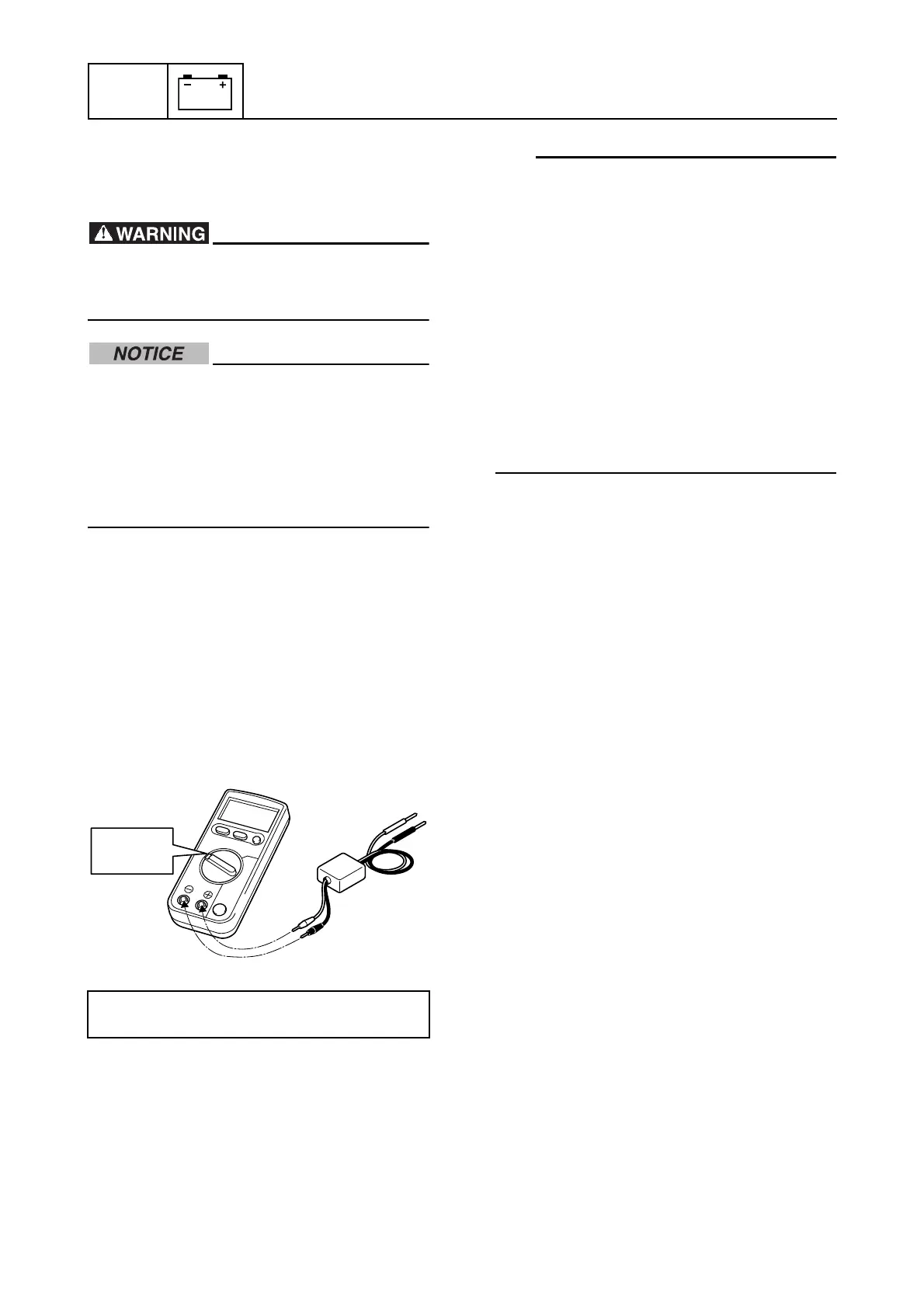
• Use peak voltage adapter B with the rec-
ommended digital circuit tester.
• Connect the positive pin of peak voltage
adapter B to the positive terminal of the dig-
ital circuit tester, and the negative pin to the
negative terminal.
• When measuring the peak voltage, set the
digital circuit tester to the DC voltage
mode.
Using the digital tester
The electrical technical data apply to the
measurements taken using the Yamaha-rec-
ommended tester.
The resistance values shown are the values
taken before the engine is started. The actual
resistance may vary depending on the envi-
ronmental conditions and ambient tempera-
ture.
Digital circuit tester: 90890-03174
Peak voltage adapter B: 90890-03172
 Loading...