0-4
How to use this manual
0
1
2
3
4
5
6
7
8
9
10
A
How to use this manual
Manual format
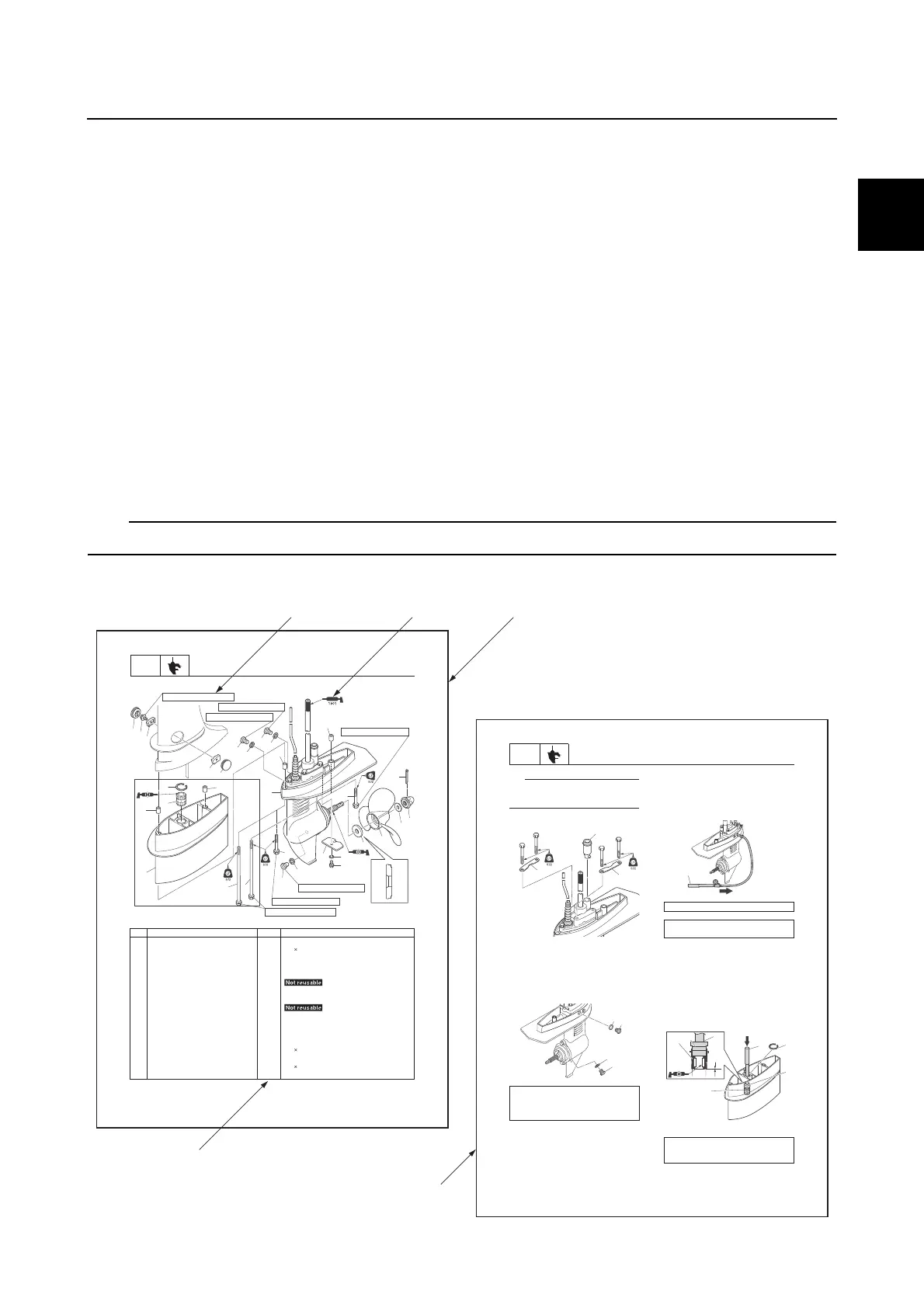
The format of this manual has been designed to make service procedures clear and easy to under-
stand. Use the following information as a guide for effective and quality service.
• Parts are shown and detailed in an exploded diagram and are listed in the component list (see a
in the following figure for an example page).
• The component list consists of part names and quantities, as well as bolt and screw dimensions
(see b in the following figure).
• Symbols are used to indicate important aspects of a procedure, such as the grade of lubricant and
the lubrication points (see c in the following figure).
• Tightening torque specifications are provided in the exploded diagrams (see d in the following fig-
ure), and in the related detailed instructions. Some torque specifications are listed in stages as
torque figures or angles in degrees.
• Separate procedures and illustrations are used to explain the details of removal, checking, and
installation where necessary (see e in the following figure for an example page).
For troubleshooting procedures, see Chapter 4, “Troubleshooting.”
8-1
LOWR
Lower unit
Lower unit
skrameRyt’Qeman traP.oN
2revoC1
6M1tlob tnioj tfihS2
20 mm
1tnioJ3
1tnioJ4
1wercs kcehC5
3teksaG6
1wercs gnihsulF7
2lewoD8
1nip rettoC9
1tun relleporP01
1rehsaW11
1relleporP21
1recapS31
14 Lower case mounting bolt 2 M6
40 mm
1rehsaw kcoL51
6M1tloB61
20 mm
1edonA71
A
1
1
2
3
4
23
8
8
23
22
21
19
19
5
6
11
14
14
18
6
17
15
16
13
12
11
10
9
16 N·m (1.6 kgf·m, 11.8 ft·lb)
15N·m (1.5 kgf·m, 11.1 ft·lb)
11N·m (1.1 kgf·m, 8.1 ft·lb)
9 N·m (0.9 kgf·m, 6.6 ft·lb)
9 N·m (0.9 kgf·m, 6.6 ft·lb)
9 N·m (0.9 kgf·m, 6.6 ft·lb)
7
6
20
11N·m (1.1 kgf·m, 8.1 ft·lb)
A L-transom model
8-15
LOWR
Lower unit
TIP:
While turning the drive shaft clockwise, push
down on the water pump housing and install
water pump housing.
8. Install the plates m and rubber seal n.
Checking the lower unit for air
leakage
1. Install new gaskets a, the drain screw b
and the flushing screw c.
2. Tighten the drain screw b and flushing
screw c to the specified torque.
3. Install the special service tool d.
4. Apply the specified pressure to check
that the pressure is maintained in the
lower unit for at least 10 seconds.
NOTICE: Do not over pressurize the
lower unit. Otherwise, the oil seals
could be damaged.
5. If the specified pressure cannot be
maintained, check the drive shaft,
propeller shaft, and rubber seal for bends
or damage, and check the shift rod
rubber seal for damage or wear.
Assembling the extension (L-
transom model)
1. Install the bushing a and circlip b.
Drain screw b:
9 N·m (0.9 kgf·m, 6.6 ft·lb)
Flushing screw c:
9 N·m (0.9 kgf·m, 6.6 ft·lb)
n
m
m
c
a
b
a
Leakage tester d: 90890-06840
Holding pressure:
98.0 kPa (0.98 kgf/cm
2
, 14.2 psi)
Driver rod L3 c: 90890-06652
Needle bearing attachment d:
90890-06615
d
c
d
a
a
c
d
b
e
b
c d
a
Safety while working / How to use this manual

 Loading...