-19-
2.2 Structure and Features of the CSU-X1
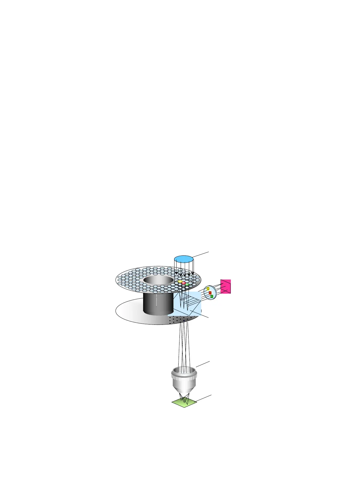
The CSU-X1 has a combination of upper and lower disks rotated by a motor. As
shown in Figure 2-2, about 20,000 microlens in the upper disk focus collimated light
from a laser on corresponding pinholes in the lower disk, which are arranged in the
same pattern as the microlens on the upper disk. The light passing through the
pinhole is focused by an objective lens on the specimen. Light from the specimen
returns along the same path through the objective lens and pinholes, is reflected by
a dichroic mirror, and is focused at a camera or eyepiece. The upper disk containing
the microlens is mechanically connected to the lower disk containing the pinholes,
and a motor rotates the both disks. Thus, the light beams can illuminate the entire
observation area of the specimen and forms a confocal optical slice at the camera or
eyepiece.
The CSU-X1 has a built-in microcomputer. It is possible to control various operations
by communication with an external computer (optional).
Figure 2-2 Basic configuration of the CSU-X1
対物レンズ
ピンホール・ディスク
検出器
標 本
焦点面
ビームスプリッター
マイクロレンズアレイ・ディスク
光源
Microlens Disk Array
Light Source
Camera
Beam Splitter
Pinhole Disk Array
Objective Lens
Specimen Focal Plane
 Loading...