EasyManuals Logo

York YCAV0157-0267 User Manual

York YCAV0157-0267
310 pages
To Next Page IconTo Next Page
To Previous Page IconTo Previous Page
Page #137 background imageLoading...
Page #137 background image
137
JOHNSON CONTROLS
FORM 201.21-NM1 (616)
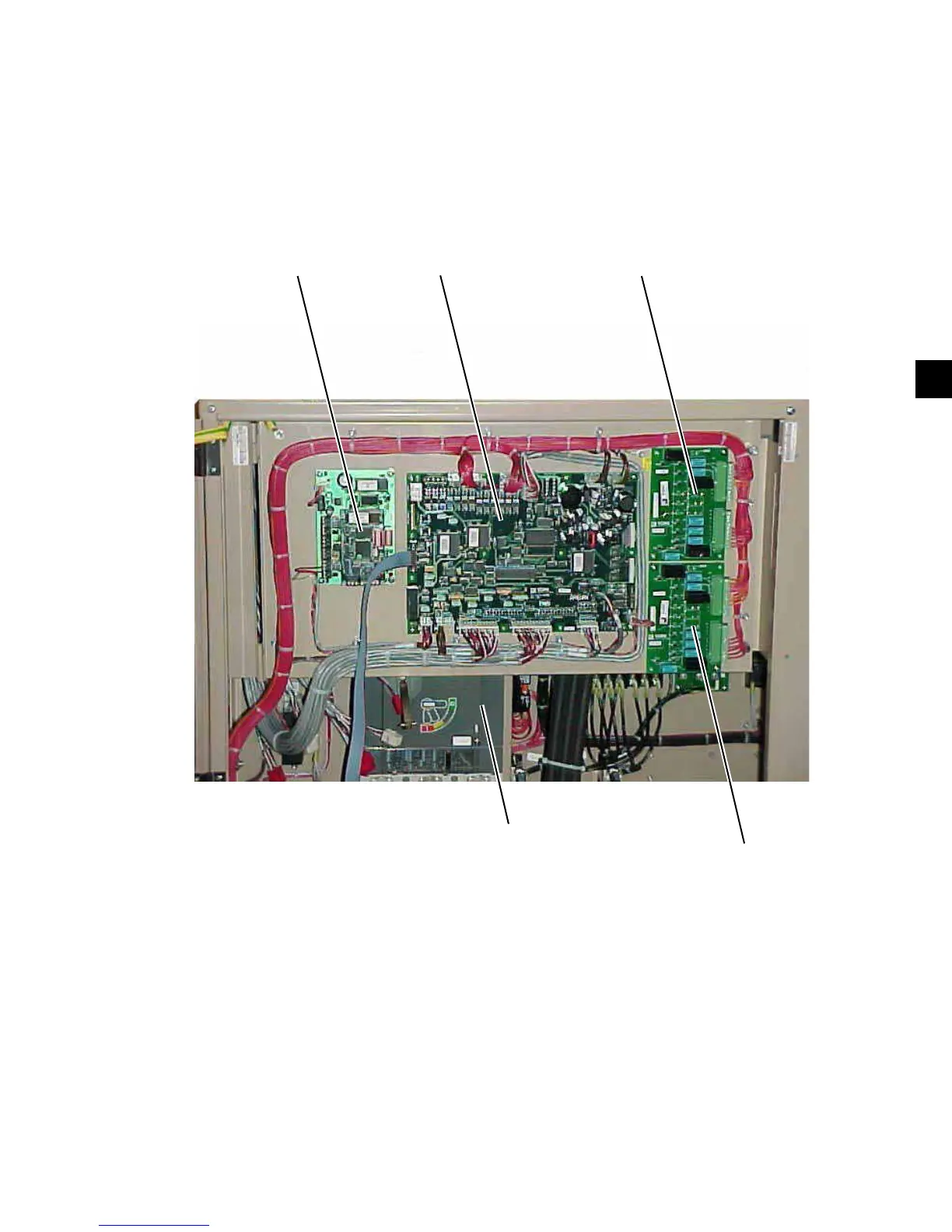
COMPONENT LOCATIONS (CON'T)
FIG. 13 - CHILLER CONTROL BOARD, RELAY BOARDS, MICROGATEWAY,
AND OPTIONAL CIRCUIT BREAKER
LD10579
MICROGATEWAY
(OPTIONAL)
CHILLER
CONTROL
BOARD
RELAY BOARD #1
RELAY BOARD #2
OPTIONAL
CIRCUIT BREAKER
(Standard Unit will have terminal blocks.
Input power to the chiller will
be connected here (see FIG.-17)).
6

Table of Contents

Questions and Answers:

Question and Answer IconNeed help?

Do you have a question about the York YCAV0157-0267 and is the answer not in the manual?

York YCAV0157-0267 Specifications

General IconGeneral
BrandYork
ModelYCAV0157-0267
CategoryChiller
LanguageEnglish

Related product manuals