165
JOHNSON CONTROLS
FORM 201.21-NM1 (616)
6
CHILLER ELECTRONIC COMPONENTS (CON'T)
Once communications is established, the Chiller Control
Board will send a data packet on the data link once every
second at 9600 baud. This data packet will include run,
stop, and speed commands as well as request operating
data from the VSD. Operating data returned by the VSD
will include individual motor currents, motor %FLA’s,
output frequency, compressor motor temperature, and
fault information related to internal VSD operating
parameters such as DC bus voltage, IGBT baseplate
temperatures, VSD internal ambient, pre-charge relay
status, power supply status, run relay status, motor
overload, and supply single phase. The Chiller Control
Board will poll the VSD Logic Board for information
continuously while the chiller is running.
IGBT GATE DRIVER BOARDS
The IGBT Gate Driver Boards provide the ON and OFF
gating pulses to the IGBT’s. The gating signals originate
from the VSD Logic Board and are changed in level by
the IGBT Gate Driver Board. The IGBT’s in the inverter
section of the VSD, change the DC Link voltage to a
variable Voltage and Frequency output to the motor, to
control the compressor motor speed. The IGBT Gate
Driver Boards also provides VCE SAT detection (short
circuit detection) to safely turn off the IGBT’s during a
short circuit condition. When a short circuit occurs, the
voltage (VCE SAT) across the IGBT increases as a result
of the high current. The IGBT Gate Driver Board is an
integral part of the IGBT assembly for each compressor.
LD10613
LD10617
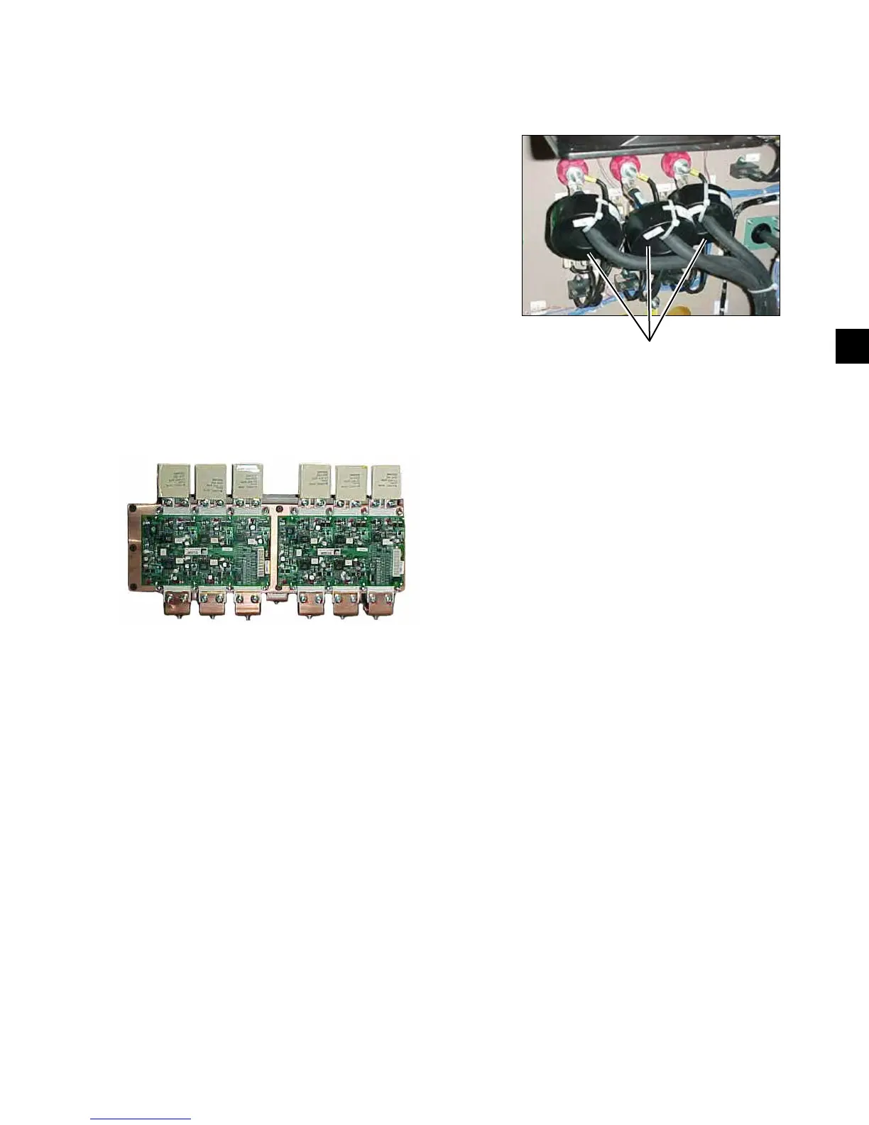
CURRENT TRANSFORMERS
A current transformer on each phase sends current
signals proportional to phase current to the VSD Logic
Board. The output of each CT is buffered, scaled, and
sent to RMS to DC converters. These signals are then
sent to an A-D converter, scaled, and sent to the Chiller
Control board for current display and current limiting
control.
The highest current is also compared to the setting of the
Overload Adjustment Potentiometer on the VSD Logic
Board for overload safety sensing.
CURRENT
TRANSFORMERS
 Loading...