278
JOHNSON CONTROLS
FORM 201.21-NM1 (616)
MICRO PANEL
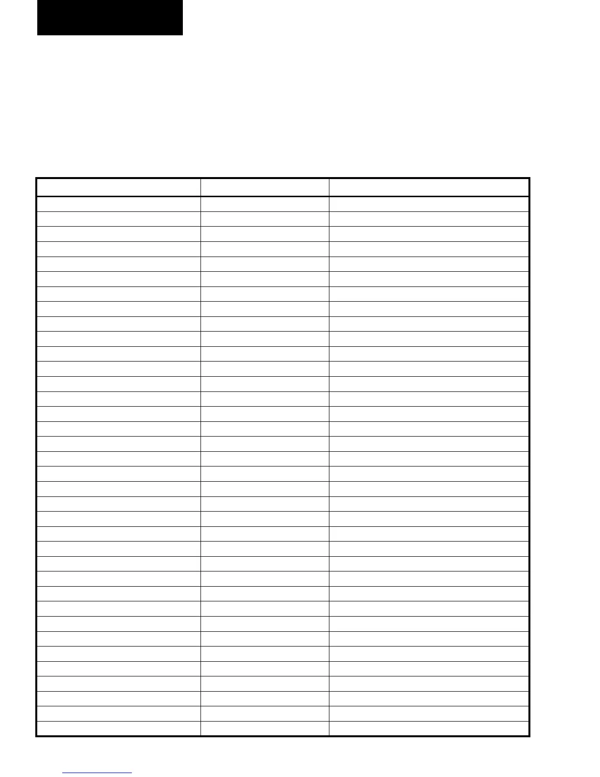
TABLE 22 - DIGITAL INTPUT CONNECTIONS
BOARD HEADER ANALOG OUTPUT
Chiller Control Board J4-2 Unit Switch 1
Chiller Control Board J4-3 Unit Switch 2
Chiller Control Board J4-4 Sys 1 HPCO
Chiller Control Board J4-5 Sys 2 HPCO
Chiller Control Board J4-6 VSD Fault Relay 1
Chiller Control Board J5-1 Sys 3 HPCO
Chiller Control Board J5-2 Sys 4 HPCO
Chiller Control Board J5-3 VSD Fault Relay (Unused)
Chiller Control Board J6-2 Flow Switch
Chiller Control Board J6-3 Print
Chiller Control Board J6-4 Sys 1/3 Run Permissive
Chiller Control Board J6-5 Sys 2/4 Run Permissive
Chiller Control Board J6-6 Spare
Chiller Control Board J7-1 to J7-2 Cong0
Chiller Control Board J7-3 to J7-4 Cong1
Chiller Control Board J7-5 to J7-6 Cong2
Chiller Control Board J7-7 to J7-8 Cong3
Chiller Control Board J7-9 to J7-10 Spare 0
Chiller Control Board J7-11 to J7-12 Spare 1
VSD Logic Board J1-10 2 Compressor Select
VSD Logic Board J1-11 3 Compressor Select
VSD Logic Board J1-12 4 Compressor Select
VSD Logic Board J5-1 to J5-2
VSD Logic Board J5-3 to J5-4
VSD Logic Board J6-2 Comp 1 Phase A Gate Driver Fault
VSD Logic Board J6-5 Comp 1 Phase C Gate Driver Fault
VSD Logic Board J6-12 Comp 1 Phase B Gate Driver Fault
VSD Logic Board J7-2 Comp 3 Phase A Gate Driver Fault
VSD Logic Board J7-5 Comp 3 Phase C Gate Driver Fault
VSD Logic Board J7-12 Comp 3 Phase B Gate Driver Fault
VSD Logic Board J7-2 Comp 2 Phase A Gate Driver Fault
VSD Logic Board J7-5 Comp 2 Phase C Gate Driver Fault
VSD Logic Board J7-12 Comp 2 Phase B Gate Driver Fault
VSD Logic Board J8-2 Comp 4 Phase A Gate Driver Fault
VSD Logic Board J8-5 Comp 4 Phase C Gate Driver Fault
VSD Logic Board J8-12 Comp 4 Phase B Gate Driver Fault
DIGITAL INTPUT CONNECTIONS
TABLE 22 lists the digital inputs and the circuit board
they are located on. The Digital input signals are typi-
cally referenced to the common (return, ground) in the
system.
J12-3 can also be used as common, as well as chassis
ground, or the common terminal point on the Chiller
Control Board. See the wiring diagrams.
 Loading...