187
JOHNSON CONTROLS
FORM 201.21-NM1 (616)
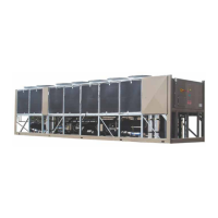
FLASH TANK DRAIN AND FEED VALVE CONTROLLER
A pair of LED’s on the left side of the module
(FIG. 33) indicate when the module is powered. The
Power LED should be lit at all times.
FIG. 33 - POWER AND COMMS LED'S
LD10630
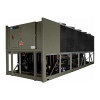
FIG. 34 -POWER, COMMS AND SYSTEM OPEN/
CLOSE LED'S
LD10631
A column of 10 LED’s runs from top to bottom on the
right side module (FIG. 34).
7
A pair of LED’s on the top of the module (FIG. 34)indi-
cate when the module is powered and when the module
is communicating with the Chiller Control Board. The
Power LED should be lit at all times.
The Open and Close LED’s on each system indicate
when the Feed and Drain valves are being driven open
or closed in an effort to control Flash Tank level and
suction superheat.These valves will light“momentarily”
when the valves are being pulsed. In most cases other
than start-up, they may appear to not light at all. The
valves that are controlled by the outputs associated with
the LED’s are decoded using the table below:
1 Open = System #1 or 3 Feed Valve Open
2 Open = System #1 or 3 Drain Valve Open
3 Open = System #2 or 4 Feed Valve Open
4 Open = System #2 or 4 Drain Valve Open
5 Close = System #1 or 3 Feed Valve Close
6 Close = System #1 or 3 Drain Valve Close
7 Close = System #2 or 4 Feed Valve Close
8 Close = System #2 or 4 Drain Valve Close
On 3 and 4 compressor chillers, a second module will
control systems #3 and #4.
Due to the short duration of the open and close stepper
pulses, LED lighting will be difcult to observe. In
rare cases where validation of the controller output and
valve movement needs to be checked, the valves can be
operated in Service Mode. When operated in Service
Mode, visual indication of the LED’s lighting will be
more obvious. Generally, no audible noise is evident as
the valves open and close unless the valve is being run
against it’s stop. It is possible to obtain an indication
of valve movement by touch, when a valve is opening
or closing.
Manually operating the Feed and
Drain Valves in Service Mode can
drain or overll the Flash Tank. This
could cause valve movements and lev-
els in the Flash Tank to act out of the
ordinary when a system rst starts, un-
til the Chiller Control Board brings the
Flash Tank level and superheat under
control. This may also be evident in
the Flash Tank level and open/close %
on the displays. It may also cause the
liquid line or Flash Tank sight glasses
to empty or the Flash Tank sight glass
to ll.
Careless use of manual control could
cause liquid damage to the compressor
when it is started.
 Loading...