169
JOHNSON CONTROLS
FORM 201.21-NM1 (616)
6
CHILLER CONFIGURATION JUMPERS (CON'T)
MAXIMUM VSD FREQUENCY/
MODEL DESIGNATOR
The model number of the chiller determines the maxi-
mum VSD frequency at 100% full speed. The maximum
frequency is programmed by factory installed jumpers
on the J7 plug of the Chiller Control Board. Three
digital inputs determine a binary code, which determines
the maximum frequency. The inputs are read as a 0 or
low when a jumper is out or a 1 or high when the wire
jumper is inserted between the two pins. The jumpers
will only be checked once by the Chiller Control Board
on power-up.
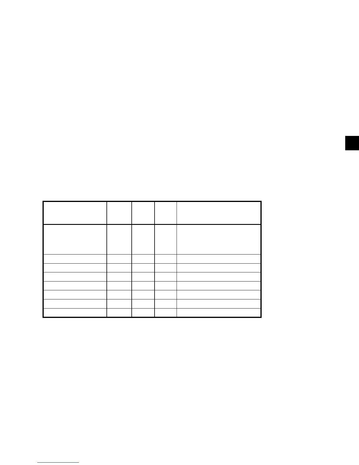
TABLE 3 shows the Chiller configuration and the
associated location of the jumpers.
TABLE 3 - MAXIMUM FREQUENCY / MODEL DESIGNATOR JUMPER
CHILLER CONTROL
BOARD MAX.
VSD FREQUENCY
J7-1
to
J7-2
J7-3
to
J7-4
J7-5
to
J7-6
YCAV
200 Hz 1 1 0 0157 SA/PA, 0177 EA/VA,
0187 SA/PA, 0227 SA/PA,
0227 EA/VA, 0247 SA/PA,
0247 EA/VA, 0267 SA/PA,
196 Hz 1 1 1
192 Hz 0 1 0 0187 EA/VA, 0207 EA/VA
188 Hz 0 1 1
186 Hz 1 0 0 0207 SA/PA, 0157 EA/VA
182 Hz 0 0 0 0177 SA/PA, 0197 EA/VA
178Hz 1 0 1
178 Hz (Spare) 0 0 1
 Loading...