101JOHNSON CONTROLS
FORM NO.: 6U6K-B01E-NB-EN
OPERATION
The Red Button
The red button can be turned to select menu elements and used
to change values. Pressing the red button activates a selected
menu element and conrms values.
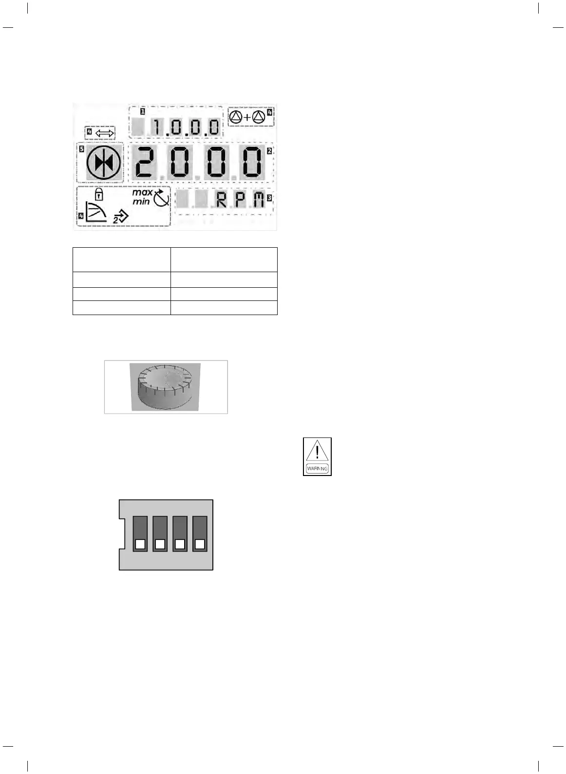
DIP Switch
The DIP switches are located under the housing cover.
•
Switch 1 is for switching between the standard and service
mode.
•
Switch 2 allows activations or deactivation of the access
disable feature.
•
Switches 3 and 4 permit termination of the multi-pump
communication.
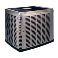
Operation
The control mode is preset as Δp-v with a delivery head of 20m.
To increase or decrease the duty point of the pump, press the
red button for 2 seconds to enter the navigation menu and make
corresponding adjustments.
Refer to the operation instruction of the pump and contact local
Johnson Controls representative for further eld settings.
Pump Settings
Units equipped with factory tted Hydro Kits are shipped with
the following settings on the pump VSD. All other settings are
default.
DIP switches S3 and S4 are set to off (single pump application).
Operation Mode is set to Δp-v.
Pump Head is set to H = 20m.
It is strictly prohibited to circulate the liquid system
with external devices in case unexpected current
induced which may damage the pump.
SECTION 6 – COMMISSIONING
Cooke Industries - Phone: +64 9 579 2185 Email: sales@cookeindustries.co.nz Web: www.cookeindustries.co.nz
 Loading...