FORM NO.:6U6K-B01E-NB-EN
JOHNSON CONTROLS
118
DEFROST CONTROLS
The purpose of any defrost system is to remove frost and ice
from the ambient coils. The adaptive defrost system achieves
this by optimizing the setpoint of defrosts dependent on ambient
temperature and duration with the aim of improving overall unit
efciency. The eld programmable setpoints are:
•
DEFROST INTERVAL (Program range 15 to 120 minutes,
40 as default)
•
DEFROST INITIATION TEMPERATURE DIFFERENCE
(Temperature difference between coil temperature and ambient
temperature; Program range -10 to 0 °C, 7 °C as default)
•
DEFROST TERMINATION TIME (Program range 180 to
600 seconds, 360 seconds as default)
•
DEFROST TERMINATION COIL TEMPERATURE
(Program range 6 to 20 °C, 10 °C as default)
The temperature sensors used are the defrost sensor(s) mounted
on the capillary of ambient coils.
The successful implementation of the adaptive defrost is
dependent on the location of the temperature sensor. The
sensor is factory positioned where in general the frost is most
persistent.
There is one defrost sensor tted on each system of the YMPA
units. Two sensors are tted on dual system units as the defrost
strategy ensures that both systems do not defrost at the same
time, which assists in maintaining some stability to the leaving
water temperature during heat pump mode. Coils defrost
normally when operating in lower ambient temperatures below
+7 °C.
Defrost Interval
The interval is the delay between defrosts within a system and
its value can be set in the range of 15 to 120 minutes with a
recommended setting of 40 minutes.
Defrost Initiation Temperature Difference
The difference between coil temperature and ambient
temperature indirectly indicates the formation of frost at the
surface of the coil. The value can be set in the range of -10 to 0
°C with a recommended setting of 7 °C.
If the temperature difference is below the initiation value, a
defrost cycle is initiated. The system mode solenoid changes
to the cooling mode. During defrost the low pressure cut-out is
ignored. The compressors within the system will start with a 30
seconds delay.
The fan for the system will stop, except when the discharge
pressure rises above 34 BARG and does not fall below
28 BARG. In this case the fan will run at xed speed. The other
system continues to operate in the heat pump mode and the unit
continues to be controlled to the heating setpoint.
Defrost Termination
When the frost is removed, the coil temperature rises rapidly
and soon reaches the termination temperature of 10°C. The
compressors will be powered off and heat loading will be
enabled.
If coil temperature is still under the termination temperature
in 360 seconds, the defrost process will also terminate. Other
protective exit criteria include discharge temperature, discharge
pressure and unit outlet liquid temperature.
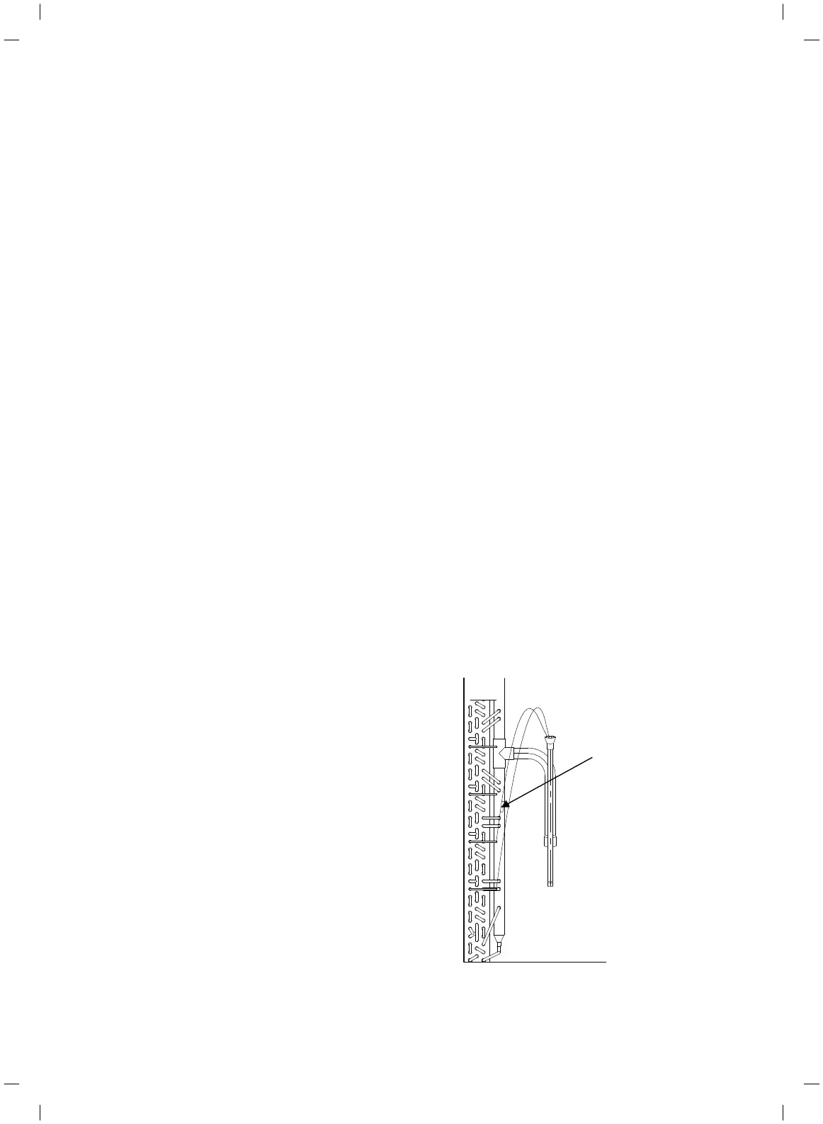
Defrost Sensor Mounting and Position
The Coil Defrost Temperature sensors are mounted on the left
hand side of the V-shaped coils on a system looking from the
side-view. Within the coil the sensor is on the second capillary
counted from the bottom. The sensor is correctly positioned
during manufacture but may need to be re-positioned at site,
to either suit site operating conditions or optimize the defrost
cycle time.
Defrost Sensor
FIGURE 45 – LOCATIONS OF DEFROST SENSOR
SECTION 9 – UNIT OPERATION
Cooke Industries - Phone: +64 9 579 2185 Email: sales@cookeindustries.co.nz Web: www.cookeindustries.co.nz
 Loading...