FORM NO.:6U6K-B01E-NB-EN
JOHNSON CONTROLS
112
SECTION 9 – UNIT OPERATION
CAPACITY CONTROL
To initiate the start sequence of the unit, all run permissive
inputs must be satised (liquid ow, remote start/stop switch,
power supply, etc.), and no unit or system faults exist.
The rst phase of the start sequence is initiated by the startup
command through HMI or daily schedule. If the unit is shut
down on the daily schedule, the chilled water pump microboard
contacts will close to start the pump when the daily schedule
start time has been reached. Once ow has been established and
the ow switch closes, capacity control functions are initiated,
if the remote cycling contacts wired in series with the flow
switch are closed.
It should be noted that the chilled water pump contacts are not
required to be used to cycle the chilled water pump. However,
in all cases the flow switch must be closed to allow unit
operation.
The control system will evaluate the need for cooling (or
heating) by comparing the actual leaving or return chilled liquid
temperature to the desired setpoint, and regulate the leaving or
return chilled liquid temperature to meet that desired setpoint.
The rate of water temperature change is also considered to
calculate the required load. If the temperature changes too fast
towards the target, the loading process will slow down to avoid
system uctuations, and vice versa.
SUCTION PRESSURE LIMIT CONTROLS
The anticipatory controls are intended to prevent the unit
from ever actually reaching a low-pressure cutout. Loading is
prevented, if the suction pressure drops below the limitations
listed in Table 31. Loading may reoccur after suction pressure
rises above the unload point and a period of one energy control
cycle.
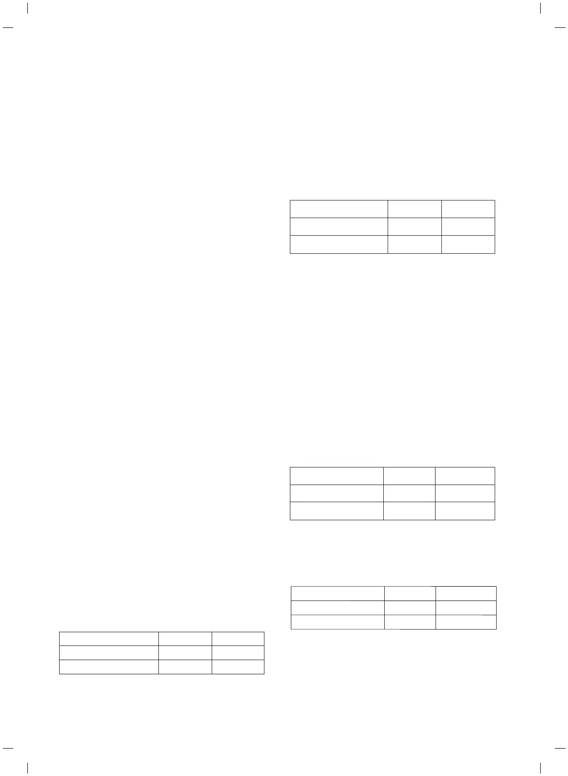
TABLE 31 - LP LOADING PREVENTION LIMITATIONS
If the suction pressure drops lower, the unit will unload to
prevent unexpected shutdown. The limitations are listed in
Table 32.
TABLE 32 - LP UNLOAD LIMITATIONS
The cooling suction pressure control is not available for glycol
applications.
DISCHARGE PRESSURE LIMIT CONTROLS
The discharge pressure limit controls prevent a system to load
or unload the system before it reaches a safety limit due to high
load or dirty condenser coils. The micro monitors discharge
pressure and decides to maintain current running load, or
unloads the compressor, when discharge pressure exceeds the
programmed setpoint. Reloading will occur when the discharge
pressure on the affected system drops below the setpoint and a
loading request is received. Table 33 lists the discharge pressure
limitations to prevent a system to load.
TABLE 33 - HP LOADING PREVENTION LIMITATIONS
The pressures listed in Table 34 indicate the limitations when
unload is mandatory.
TABLE 34 - HP UNLOAD LIMITATIONS
COMPRESS RATIO LIMIT CONTROLS
Compress ratio is calculated by absolute discharge pressure
divided by absolute suction pressure. In most cases, the
Cooling Heating
Fixed Speed SYS. 720 kPa 300 kPa
Inverter SYS. 670 kPa 200 kPa
Cooling Heating
Fixed Speed SYS. 615 kPa 200 kPa
Inverter SYS. 650 kPa 190 kPa
Cooling Heating
Fixed Speed SYS. 3100 kPa 3250 kPa
Inverter SYS. 3420 kPa 3420 kPa
Cooling Heating
3800 kPa 3750 kPa
3490 kPa 3490 kPa
SECTION 9 – UNIT OPERATION
Cooke Industries - Phone: +64 9 579 2185 Email: sales@cookeindustries.co.nz Web: www.cookeindustries.co.nz
 Loading...