EN 7
Safety instructions
Read the following instructions carefully before proceeding with the
installation.
Warning! Dangerous voltage!
Only a competent electrician may install ACS55.
Never work on the drive, the motor cable or the motor when main
power is applied. After switching off the input power, always wait at
least for 5 minutes to let the intermediate circuit capacitors
discharge before you start working on the drive.
Warning! If the heat sink is not earthed properly, you can get an
electric shock if you touch the heat sink.
Note: DIP switches are at a dangerous voltage.
Note: Even when the motor is stopped, dangerous voltages are
present at power circuit terminals L/R, N/S, T1/U, T2/V and T3/W.
Note: Even when the unit is powered down, there may be
dangerous external voltages connected from outside to the relay
output terminals.
Warning! Hot surfaces!
During operation, the cooling element may reach high temperature
(>80°C). Make sure to follow the installation instructions.
General safety instructions
ACS55 starts the motor automatically after a supply break if the
external start signal is on.
Never attempt to repair a broken unit. ACS55 is not a field
repairable unit. Contact the supplier for replacement.
Install ACS55 in a locked or tool-openable space.
Do not connect input power to the unit more than once every three
minutes.
Altering the DIP switches will affect the function and performance
of ACS55. Check that the changes will not cause any risk to
persons or property.
About this manual
This guide provides information necessary to install and start-up
the unit.
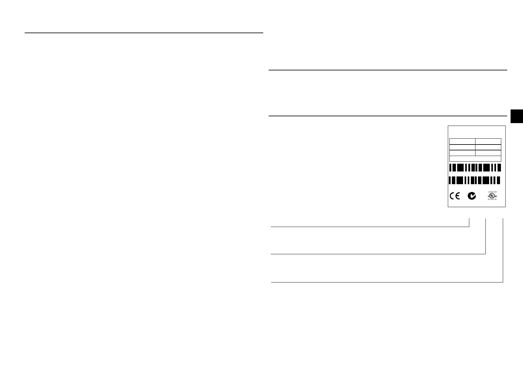
Delivery check
Serial number (S/N) is printed on the rating plate.
(Y = manufacturing year, WW = manufacturing week)
8
I
,
8
I
,
$&6($
,3
61<::5;;;;
$)(;;;;;;;;
3QPRWRUN:+3
a9
+]
$
a8
+]
$
5R+6
ACS55-01_-____-_
The delivery includes:
1. ACS55
2. User’s guide
3. Two clamps for the control cable (EMC units
only).
Check the rating plate and ensure that the
delivered device corresponds to the order.
EMC filter: E = Built in, N = No
Max. continuous output current (I
2
):
01A4 = 1.4 A, 02A2 = 2.2 A, 04A3 = 4.3 A,
07A6 = 7.6 A, 09A8 = 9.8 A
Supply voltage (U
1
):
1 = 110…120 VAC +10%/-15%
2 = 200…240 VAC +10%/-15%

 Loading...


