QUICK START
TUBING CONNECTIONS
B - 5
TUBING CONNECTIONS
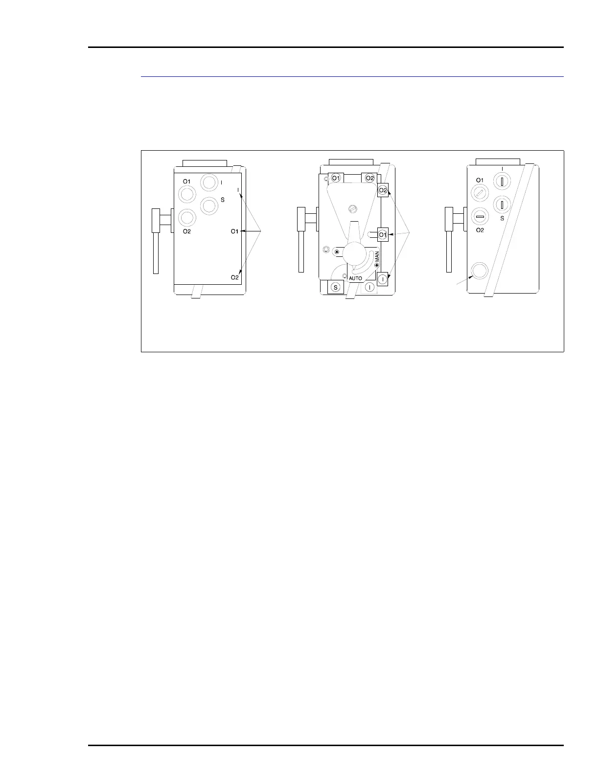
1. Connect the required supply air to connection S (Fig. B-5).
NOTE: Maximum torque for ¼-NPT fittings is 13.6 Nm (10.0 ft-lbs).
2. Based on the positioner type, perform one of the following steps
(Fig. B-5):
• AV11 and AV15: Connect 20.7 to 103.4-kPa (3.0 to 15.0-psig)
instrument signal to connection I.
• AV12 and AV16: Connect 20.7 to 186.2-kPa (3.0 to 27.0-psig)
instrument signal to connection I.
• AV2: Connection I is not used and should be plugged. If it is not
plugged, do so at this time.
NOTE: Use liquid or paste pipe sealant to seal the connection. Max-
imum torque for ¼-NPT fittings is 13.6 Nm (10.0 ft-lbs).
3. Connect the output ports 01 and 02 as required to provide the
desired direction of rotation. Figures B-6, B-7, B-8 and B-9 show a
single acting tubing example, and Figure B-10 shows a double acting
tubing example.
NOTE: The piping arrangements shown in Figures B-6, B-7, B-8,
B-9 and B-10 are general examples and may not reflect the arrange-
ment required for the application.
4. Install -NPT permanent instrument gages to the gage ports if
desired or for calibration requirements.
Figure B-5. Port Locations
T00806A
VIEW WITH GAGE
BLOCK (AV???3???)
VIEW WITH MANIFOLD
(AV???1??? OR
AV???2???)
VIEW WITHOUT
MANIFOLD
(AV???0???)
GAGE
PORTS
GAGE
PORTS
CONDUIT
CONNECTION
 Loading...


