REPAIR AND REPLACEMENT
REPLACEMENT PROCEDURES
8 - 2
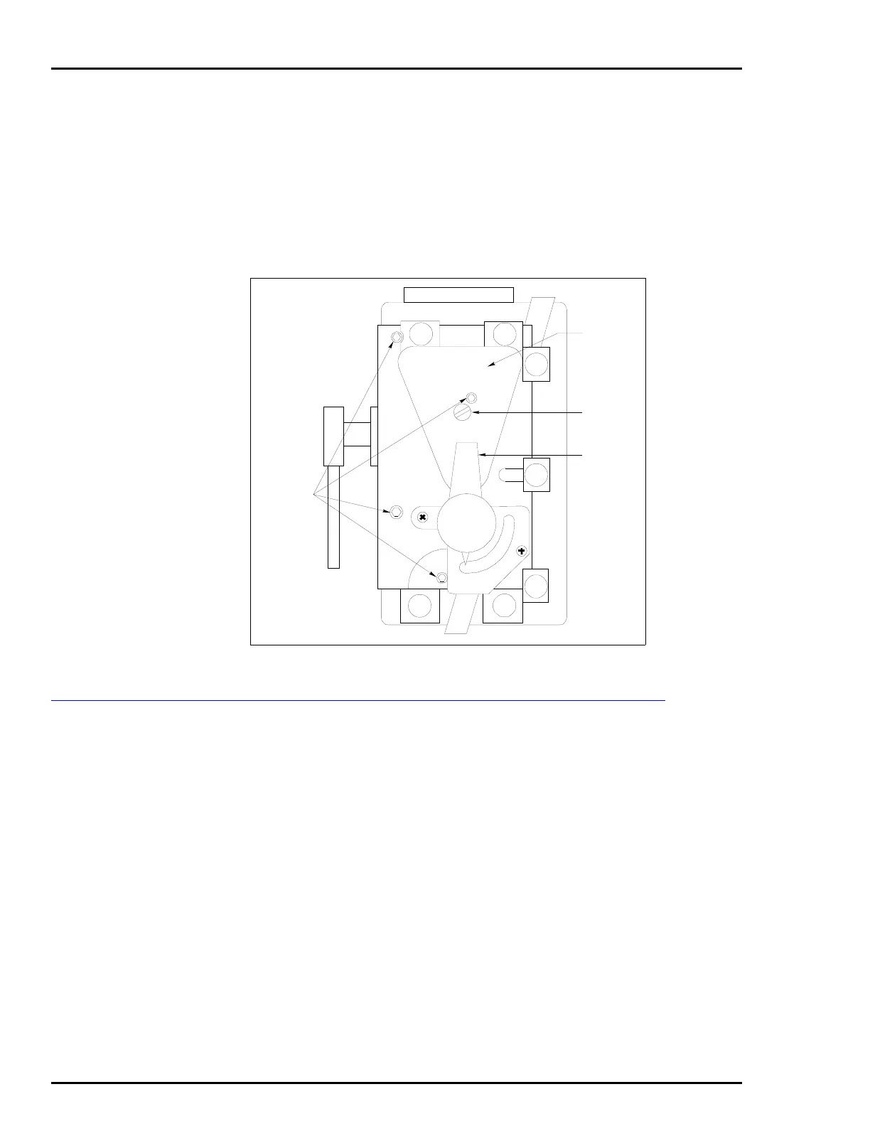
8. Place the manifold in place on the positioner so it properly seats
on the bosses.
9. Insert the Allen screws and torque them to 3.5 Nm (31 in.-lbs).
Not all of the Allen screws are the same length. Be sure each screw
mates correctly.
10. To replace the filters and filter cover, refer to MANIFOLD FIL-
TERS in Section 7.
Gain Hinge Spring
NOTES:
1. Refer to Table 4-1 for gain hinge spring part numbers.
2. Item numbers in this procedure reference Figure 9-3 or 9-4.
Tools Required:
• Flat-tip screwdriver.
• -inch Allen wrench.
1. Transfer the positioner from automatic to manual operation
(Section 5).
2. Remove the positioner cover by removing the two cover screws.
3. Remove the plug button (Item 29) from the positioner housing.
This opening provides access to the screws.
Figure 8-1. Positioner with Manifold
T00738A
COVER
SCREW
FILTER
COVER
VALVE
HANDLE
ALLEN
SCREWS
S
AUTO
O2
O2
O1
O1
I
I
MAN
 Loading...


