POSITION TRANSMITTERS
CALIBRATION
A - 2
CALIBRATION
There are two procedures for calibration; one for the potentiomet-
ric option (Type AV
____1__) and another for the four to 20-milli-
amp option (Type AV
____2 __).
Calibrating the Potentiometric Position Transmitter
This calibration example using the potentiometric position trans-
mitter can be used as a guide for other applications. Final calibra-
tion of the potentiometric position transmitter option depends on
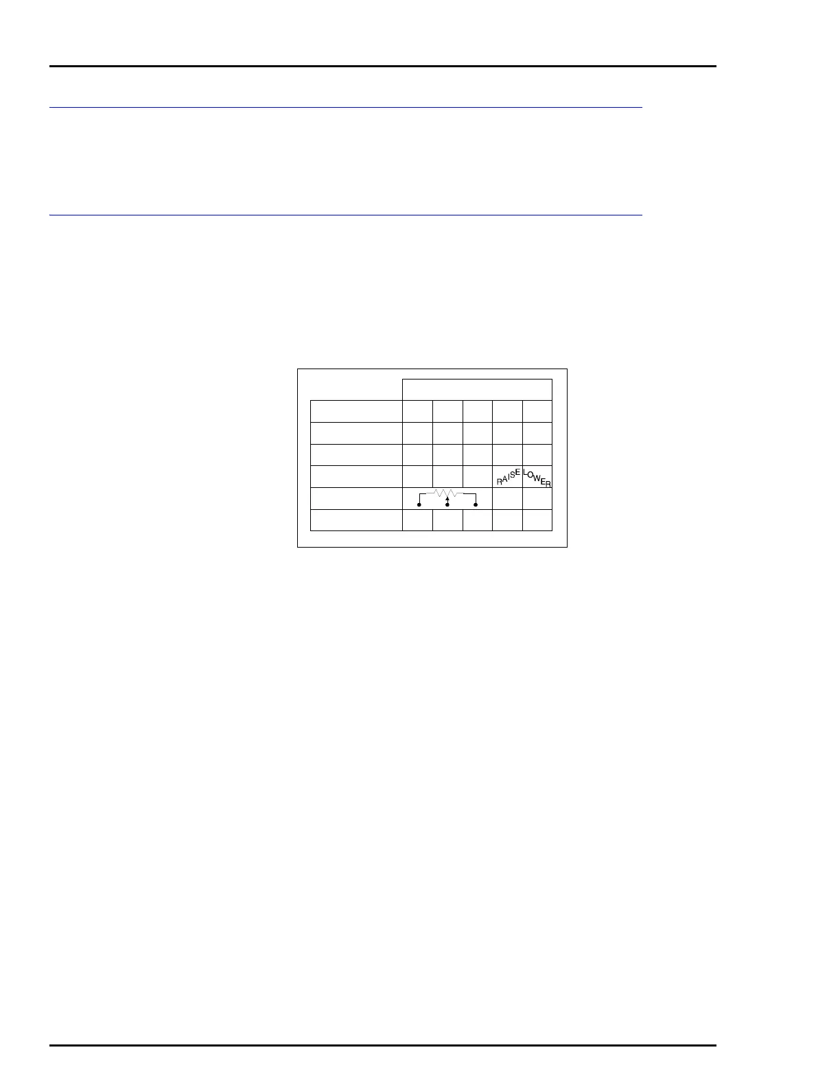
the application. Field connections to the potentiometer are shown
on a label located inside the positioner cover. The label is shown
in Figure A-1.
The nomenclature and terminal connections of Figure A-1 are:
AV23
The positive (+) and negative (-) connections at position TB1-4
and TB1-5 refer to the four to 20-milliamp signal to the I/P con-
verter.
AV33
Not applicable.
AV44
Not applicable.
AV____1__
Depicts the connections for the potentiometric position trans-
mitter option.
AV____2__
The positive (+) and negative (-) connections at position TB1-1
and TB1-2 refer to the output signal from the four to 20-milli-
amp position transmitter.
Direct acting cam rotation of zero to 100 percent produces
increasing resistance between terminal block TB1-1 and TB1-2.
Reverse acting cam rotation of zero to 100 percent produces
decreasing resistance between TB1-1 and TB1-2.
Figure A-1. Terminal Block Connections
NOMENCLATURE
AV23?????
AV33?????
AV44?????
AV????1??
AV????2??
123
TB1 CONNECTIONS
T00807A
45
+–
+–
+–
+24
+–
 Loading...


