INSTALLATION
MOUNTING TYPE AV POSITIONERS
3 - 6
Due to the wide range of applications that the Type AV positioner
is suited for, we can only provide general information about
mounting. Use the following procedure to mount the positioner.
1. Set the actuator at the zero position. Connect the adjustable
linkage to the drive arm. The drive arm holes correspond to stroke
length of the actuator. Refer to Figure 3-3 for the stroke length for
each drive arm hole.
2. Install the cam (black, direct acting; or red, reverse acting) that
will provide the required direction of rotation.
A direct acting (black) positioning cam with segments A, B and C
(Fig. 3-7) and a reverse acting cam are furnished with each posi-
tioner. The reverse acting cam has red radial lines and arcs and
is stored on the inside of the positioner cover. Cam A is for a
square root function, cam B is for linear motion and cam C is for a
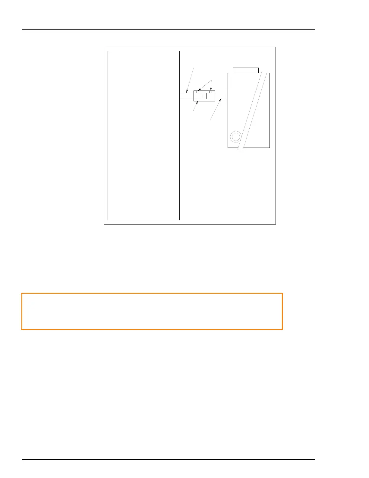
Figure 3-6. Mounting Using Direct Coupling (Typical)
AV?????1?
POSITIONER
T00803A
ROTARY ACTUATOR
ACTUATOR
SHAFT
AV O U TPUT
SHAFT
COUPLING
SET
SCREWS
WARNING
Before mounting or installing positioner, check nameplate
data to make certain positioner is suitable for application
desired. DO NOT AT ANY TIME EXCEED THE RATINGS
LISTED ON THE NAMEPLATE.
 Loading...


